• The move to the new server is done. There are some software and database maintenance updates in process. This has us passing the hat around to help out. We appreciate any donations. Seriously, even a dollar helps. The payment page may be found here - https://www.audiokarma.org/support.html

Marantz 2325 has high THD in both channels

Yours looks like pin 3 is connected to ground?
index.php

Yes, this looks like how it is wired. Testing with two ohmmeters showed it working smoothly.

Here's a simple test that is similar to your balance control test, except without using the control.
Disconnecting each main amp one at a time from the preamps gave the same result as with the balance control. When either amp is disconnected, the other amp works.

Next I will do the most recent suggestions from @dr*audio and @rBuckner.
 
You need to use a scope and look for ripple
I used a DMM to detect AC in the power supply outputs. The 2325 with the issue shows 1.5mVAC, and it stays the same with or without a load. I did the same test on another 2325, which showed 0.8mVAC. Are these values acceptable?

I used the DMM as I do not know how to do the measurement with my scope or if it is sufficient to do it. I have 2 Fluke DMM's. The older 23 could not measure it, but the newer 176 "true RMS" model does.
 
@dr*audio one more observation: After powering off, the 2325 with the issue climbed to 1.7mVAC and stayed there, while the other 2325 eventually dropped to 0.2mVAC.
 
I suggest testing the amps separately at the specified output levels by directly driving the Main In jacks.
Using the Main In jacks it works fine, typical distortion levels all the way up to maximum specified output. If I can convince the owner to use it just as a main amplifier then everything will be OK.

Also test just the preamp outputs at various output levels of the volume control at both -10dBv and 0dBv generator levels.
At 3V output from the preamps THD is 0.15% @ -10dBV. And 0.08% @ 0dBV. I did not expect that result. It's good to know that -10dBV is the standard unbalance signal level.
 
A couple of observations, suggestions:
  • The Main Amp is fed from +60V & -60V from a separate transformer secondary from the other circuits.
upload_2023-5-14_8-41-59.png
  • My guess is that the issue may be in the Main Amp (or power to it), rather than the PreAmp since disconnecting one or the other Main Amp jumpers eliminates the problem
  • The input line AC goes through a full-wave bridge rectifier, then a couple of huge 15,000uF filter caps that feeds the +/-60V
  • You can check the +/-60V using your scope, but you will need 10X probes and be sure to attach the ground to chassis ground, not the signal
  • Set the scope to DC coupling and measure the voltage (both + and -), waveforms should look clean
  • Then, set the scope to AC coupling to measure the ripple (you will need to probably go to millivolt scale)
  • Check this both when one Main is connected, and when both connected and see if the waveform or ripple changes.
One more thing to check is each P700 board has a coax audio input cable (RCA) that goes from the Main In jack to J701. Make sure that the cable is good, clean, and good ground.
You can also measure the +/- 60V at J710 to make sure it looks clean and OK also.
 
I used a DMM to detect AC in the power supply outputs. The 2325 with the issue shows 1.5mVAC, and it stays the same with or without a load. I did the same test on another 2325, which showed 0.8mVAC.
Where did you measure this?
After powering off, the 2325 with the issue climbed to 1.7mVAC and stayed there, while the other 2325 eventually dropped to 0.2mVAC.
Where was this measured? 35VDC output? With power off, you should not see any AC.
Wait a minute... If you take this same measurement, but now unplug the AC plug from the socket, do you still see the AC?
If not, then maybe some AC is leaking through even with the switch in the off position. There is a cap/resistor G001 "Printed Compo." that is across the main power switch contacts when the switch is off. Maybe this is bad? Someone else can answer this???
 
Last edited:
You need to use a scope. Most DMMs don't have enough bandwidth and anyway you don't know what you are looking at. 60Hz? 1KHz? 20KHz? No way to know.
 
Using the Main In jacks it works fine, typical distortion levels all the way up to maximum specified output. If I can convince the owner to use it just as a main amplifier then everything will be OK.


At 3V output from the preamps THD is 0.15% @ -10dBV. And 0.08% @ 0dBV. I did not expect that result. It's good to know that -10dBV is the standard unbalance signal level.
I suggest trying the same measurement again that showed the issue but at the -10dBv drive level. It may be fine now. And wouldn't that be nice?!
 
Also check that RE11 and RE12 are 150K on the BA312 ICs on the tone amp board(s) that you have. Probably are but worth a check.
 
Where was this measured? 35VDC output? With power off, you should not see any AC.
Measured across J805 (35VDC) and ground. The reading of 1.5mVAC continues after the switch is turned off. It does not go down until the receiver is unplugged. Plug it back in and it goes back up to 1.5mVAC with the power switch still off.

I checked another 2325 again to verify that it drops to 0.2mVAC after switching off but leaving plugged in. It remained there after being unplugged.

The power switch was replaced as was the snubber G0001. The replacement snubber was installed at the AC outlets rather than on the power switch. I wonder if I put it in the wrong place? Nope, just removed it with no change.

A test of resistance across the power switch (unplugged of course) when turned off shows 2.9M ohms (is that the right way to state that?).

One more thing to check is each P700 board has a coax audio input cable (RCA)
I bypassed the connection from the Main In to the amp inputs using a pair of RCA cables from the Pre Out to the RCA on the amps. No change.

I'll follow-up on the scope suggestions next.
 
You can check the +/-60V using your scope, but you will need 10X probes and be sure to attach the ground to chassis ground, not the signal
Using a 10x probe I connected the scope to the plus side (red wire) coming off the bridge rectifier and to chassis ground. No signal being applied to the inputs and no load. I am not clear if this is needed or not.

Set the scope to DC coupling and measure the voltage (both + and -), waveforms should look clean
I'm unable to adjust the scope to see a waveform. Whatever is there is way off the screen.

Then, set the scope to AC coupling to measure the ripple (you will need to probably go to millivolt scale)
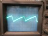
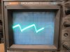
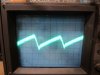
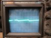
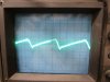
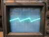
Adjusting down to the millivolt scale a waveform appeared. Sharply focused when audio cables to both amps connected, fuzzy when one amp is disconnected, fuzzier still with both amps audio cable disconnected:
1 both amps connected to audio_resize.JPG , 2 one amp connected to audio_resize.JPG , 3 neither amp connected to audio_resize.JPG

Testing disconnecting the power to the amps, pictures show power to neither amp, to one amp, and to both amps:
4 power to neither amp_resize.JPG , 5 power to one amp_resize.JPG , 6 power to both amps_resize.JPG

Are these pictures showing ripple? If not, I'll deeply appreciate more instruction on how to make the measurements.
 
Thanks. I wouldn't expect to see ripple with 15,000 uF capacitors, especially with no load. Do you remember what the vertical scale was and did you use a 10x probe or 1x? What was the horizontal timebase?

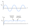
Here's what a full wave rectifier with filter capacitors should look like.
upload_2023-5-14_20-54-36.png
Looks similar to what you have except with no load on the PS, there should not be any ripple?
 
Last edited:
I suggest trying the same measurement again that showed the issue but at the -10dBv drive level. It may be fine now. And wouldn't that be nice?!
It sure would be nice. But THD measured the same at the -10dBv drive level.

Also check that RE11 and RE12 are 150K on the BA312 ICs on the tone amp board(s) that you have.
Both resistors measure just below 150K.
 
Do you remember what the vertical scale was and did you use a 10x probe or 1x? What was the horizontal timebase?

1x probe
Volts/div 50mV
Time/div 2mS

Set the scope to DC coupling and measure the voltage (both + and -), waveforms should look clean
I'd like to be able to do this measurement. When I tried to do it, whatever was being displayed "dropped down" off the screen, and I was not able to adjust it back. I'm missing something obvious...
 
60VDC may be too much for your scope input. First, look to see what your maximum CH1 scope input voltage knob is. Probably 5V/div. If you have 8 vertical divisions, 8*5=40V, not enough for the 60V. If you use a 10x scope probe (usually a switch on the probe), then a 50 volt signal will look like a 5V signal (/10). So a 60VDC signal should be a little over 1 division. Or, you can look at the AC portion of the signal. This is usually the noise that rides on top of the 60V DC. When you select AC on the scope, the 60V DC is filtered out and all you have left is the AC portion of the waveform that is riding on top of the 60V.

So, in your case you have 60V with about 2 divisions of ripple on top of it (2 x 50mV = 100mV or 0.1V). Probably OK for a 60V DC power.
 
New data. If the right main amp is swapped out with a known working one, the issue goes away. If instead the left amp is swapped out, the issue remains. The right amp is not playing well with others?

The thing is playing now with a temporary right amp and the original left. THD is well within spec in both channels at both 0dB and -10dBv drive levels. It's working just like I'm used to seeing.

For those following along, I reported way back that the right amp had been swapped out at some point, but in reviewing my notes I saw only the left had been. So I did it now just to be sure, even though I did not expect any change. And look what turned up!

Tomorrow I'll do some amp swapping to my shop 2325 to verify it really is just this one amp module misbehaving, and then deal with it.
 
I had thought that possibly the power supply or ground for the preamp (not the main supply) was being modulated when the unit was run into a load. Your swapping out the right channel amps proved that this is not the case.
I now suspect that the right channel amp is oscillating. Reinstall it, connect the preamp outs to power amp inputs, and connect a load, but do not apply input. Set your scope to AC coupled input, 200mV/Div, 2mS/Div and use a 10X probe if you have one. Connect the probe to the left channel speaker output and ground and show us what you see. Set the horizontal sweep to 2uS/Div and take another picture.
 
Back
Top Bottom