• The move to the new server is done. There are some software and database maintenance updates in process. This has us passing the hat around to help out. We appreciate any donations. Seriously, even a dollar helps. The payment page may be found here - https://www.audiokarma.org/support.html

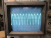
Marantz 2325 has high THD in both channels

This is with loads connected and preamp out to poweramp in connected?
And the original amp in the right channel?
Yes to loads. But I had connected the Pre Out jacks directly to the RCA plugs on the amps. Now the Main/Pre jacks are jumpered.

Left channel, edit: new left channel pictures coming


Right channel:
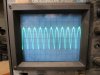
200mV/Div, 2mS/Div
2325 right 200mV 1mS_resize.JPG

200mV/Div, 2uS/Div
2325 right 200mV 1mS_resize.JPG

20mV/Div, 1uS/Div:
2325 right 20mV 1uS _resize.JPG
 

Attachments

  • 2325 left 200mV 1mS_resize.JPG
    2325 left 200mV 1mS_resize.JPG
    87.6 KB · Views: 6
  • 2325 left 200mV 1uS_resize.JPG
    2325 left 200mV 1uS_resize.JPG
    88.5 KB · Views: 6
Last edited:
Some issues with labeling in posts 41, 42, 43. Hopefully this will clarify.

As requested, more simple

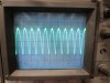
Left channel, 200mV/Div, 1mS/Div:
2325 left 200mV 1mS_resize.JPG

Left channel, 200mV/Div, 1uS/Div:
2325 left 200mV 1uS_resize.JPG

Not requested but noted
Left channel, 20mV/Div, 1uS/Div, with audio cable disconnected:
2325 left 20mV 1uS .JPG

Right channel, 20mV/Div, 1uS/Div, with audio cable disconnected:
 
As I guessed, it's oscillating. I thought the right channel amp is the bad one but you only seem to have looked at the left channel with the scope. Your posts are a bit confusing on this.
Check both channels. The one that has higher amplitude on the waveform is the one that is oscillating.
Did you replace any transistors?
 
Just a couple of questions.
  • These are with internal PreOut to Main In jumpers, or external RCA cables from PreOut to Main In?
  • No signal input, Selector set to Aux, speaker outputs on?
  • Was your scope probe on 1X or 10X and in post #44 are the XX mV/div the dial value or the 10X value?
  • Are these photos AC coupled input?
  • Were these taken on the speaker terminals?
  • These are with the "good" P700 board or the bad one?
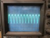
  • That doesn't look like typical sinusoidal oscillation, but more like a full-wave rectified waveform.
 
Last edited:
Your posts are a bit confusing
Yes. I started doubting my labeling and testing and then I made the posts worse. I'll run the tests again.

Just a couple of questions.
External RCA cables from Pre Out to Main In.
No signal input, Selector on AUX, speaker outputs on
I used 10x, mostly. I'll keep better track this time.
AC coupled input
At the speaker terminals
The original boards including the "bad" one

I did do one other test, and that was to put a pair of known good amps in the unit we're working on. It tests great. Low THD throughout the volume range. Which seems to demonstrate conclusively that the issue is with one or both of the original amps. Later today I'll put the original amps back in and run the tests again. Thank you both for your continuing help.
 
Thanks. You used a 10X probe, is the 20mV/div the reading on the vertical knob setting, or is it the knob x10?
 
Here are the test results hopefully more clear.

Settings

  • Main In/Pre Out jacks connected externally
  • Measured at the speaker terminals
  • Original amps
  • 8 ohm load
  • AC
  • 10x

Audio input cables plugged into the amps

200mV/div,1mS/div
200mV/div,1uS/div
20mV/div,1uS/div
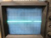
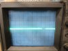
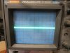
For all three settings the right and left channels each show just a horizontal line IMG_8599_resize.JPG

Audio input cables unplugged from the amp being tested

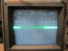
Right channel, audio unplugged:

200mV/div,1mS/div IMG_8584_resize.JPG

200mV/div,1uS/div IMG_8588_resize.JPG


20mV/div,1uS/div IMG_8590_resize.JPG


Left channel, audio unplugged:

200mV/div,1mS/div IMG_8593_resize.JPG

200mV/div,1uS/div IMG_8595_resize.JPG

20mV/div,1uS/div IMG_8591_resize.JPG

It's hard to tell in the pics but the right amplitude is higher than the left.
 

Attachments

  • IMG_8585_resize.JPG
    IMG_8585_resize.JPG
    75.1 KB · Views: 5
  • IMG_8586_resize.JPG
    IMG_8586_resize.JPG
    79.6 KB · Views: 4
Audio input cables unplugged from the amp being tested
You are saying:
Selector on what.... Aux?
By "Audio input cables" are you talking about unplugged from Aux input, or PreOut to Main In?
  • Ch 1 set at 20mV/div,
  • 10x probe means input to probe is 0.2V/div,
  • noise is 4 div (p-p) so 0.2V x 4 = 0.8V p-p of (sort of sinusoidal) noise?
  • Correct??
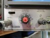
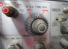
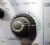
In you photo of the time base control, it looks like your center knob is pulled out, you need to align the white marks to the larger pointer and push it in, otherwise you don't know the frequency.
 
Last edited:
When one channel is oscillating, it couples into the other channel, but the oscillation will be higher from the bad channel.
 
I mean the RCA plugs on the amplifiers themselves.
Sorry, I'm still unclear. Let's try this again. What do you mean by "RCA plugs on the amplifiers"? "Audio input cables unplugged" means no RCA cables plugged into the Aux input... or the RCA cable that jumpers PreOut to Main In is unplugged? The reason that I ask is that I may ask you to short the input conductor to the ground shield to see if the oscillation goes away.

Just a bit of terminology:
Jack = RCA receptacle (female) on the receiver
Plug = RCA cable end (male) on the audio cable​
 
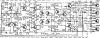
C713 is a Miller cap, the purpose of which is to prevent oscillation. You might want to replace them on both amps and see if that fixes it. Use a ceramic cap with NPO/COG dielectric constant.
 
Let's try this again,
upload_2023-5-16_15-23-4.png
You have time delay - Off
Variable Hold - Off
A timebase = 1 msec
B timebase = 0.1 msec
How do you read 1us/div, or was that when you measured 1 ms/div?
 
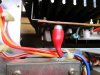
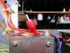
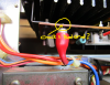
Looks like a crack PC board here! Check the traces on the back side. Poor ground could cause an oscillation also. Is this the board that is giving you problems?
Also when unplugged, you probably should have a shorting plug to ground the input signal. You can use an RCA cable plugged in and at the other end, connect center conductor to outer conductor (shield). See if oscillation goes away.
upload_2023-5-16_15-44-10.png
 
Last edited:
You have time delay - Off (should this be on for these tests?)
Variable Hold - Off (should this be on for these tests?)
A timebase = 1 msec
B timebase = 0.1 msec (now zeroed out, aligned with A timebase dial)
How do you read 1us/div, or was that when you measured 1 ms/div? IMG_8607.JPG
 
Back
Top Bottom