• The move to the new server is done. There are some software and database maintenance updates in process. This has us passing the hat around to help out. We appreciate any donations. Seriously, even a dollar helps. The payment page may be found here - https://www.audiokarma.org/support.html

Marantz 2325 Left Channel Pre Has No Output

richardg0n

Active Member
Hi Guys,
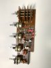
I recapped the pre-amp board (PE01) on my 2325 and am not getting any output on the left channel. I am running a sine wave from an audio generator into the AUX RCA inputs and am monitoring through the headphones and Tektronix 465. I am only getting output on the right channel in the headphones.

Using Tektronix 465 I can see the input coming in on pin 7 for the left channel of the PE01 board. I have the schematic and can't seem to figure out the signal path(I am a schematic newbie and reading a few books on schematics). I also checked my solder points and used a DMM to check continuity between the points with no issues. I pulled and checked transistors H03, HE04, HE05, HE06 with an Atlas DCA55 and DMM with no issues. I also used Deoxit D5 to clean the pods with no change. I did notice a little hum on left channel headphones when switching between tone modes switcher SE01.

I don't know how to proceed. How would you troubleshoot this problem? Thanks in advance for your input.
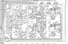
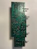
PE01.jpg IMG_6119.jpg IMG_8737.jpg
 
Register to hide this ad
Welcome to AudioKarma!

Test for output from the PE01 at the Pre-Out jacks and confirm only one channel is working there.
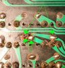
Thanks for the pictures. Can you provide a higher resolution picture of the bottom (foil) side of the board? There are some solder connections I'd like to look closer at.
 
Welcome to AudioKarma!

Test for output from the PE01 at the Pre-Out jacks and confirm only one channel is working there.
Thanks for the pictures. Can you provide a higher resolution picture of the bottom (foil) side of the board? There are some solder connections I'd like to look closer at.

To confirm where are the Pre-Out jacks on the board/schematic? How should I test it? Oscilloscope or DMM?

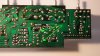
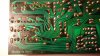
See attached pictures of the bottom of the board.

PANA3260.JPG PANA3261.JPG
 
Thank you for the pictures.

Please check for continuity between the two points in the arrows:
richardg0n PE01 foil6.jpg

And if you can, provide a closer/higher resolution picture of this area:
richardg0n PE01 foil5.jpg

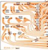
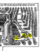
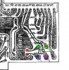
Here is a clean scan of the board layout, flipped to show the traces in the picture above:
2325 PE01 board layout diagram clean scan reversed detail.jpg
 
  • Like
Reactions: mbz
Yes, I am getting a continuity reading on the first picture between the two points.


Closeup of other area below.


PANA3262.JPG
 
Thanks for the picture. You have probably already done this, but check for continuity. The upper points in the picture should show continuity, the lower points in the picture should not.

richardg0n foil side detail w arrows.JPG
 
To confirm where are the Pre-Out jacks on the board/schematic? How should I test it? Oscilloscope or DMM?

See attached pictures of the bottom of the board.

View attachment 1749868 View attachment 1749878
The Pre Out jacks are on the back of the receiver. Randy wants you to check for signal there to verify no left pre signal. You can plug an RCA cable into the jack and look for signal on the other end of your cable with your scope. Older Marantz units had an external jumper to connect the Pre Out to the Main In. That way they could be separated if needed. The 2325 has internal jumpers that connect the Pre Out to the Main In. When you plug an RCA connector into the Pre Out, it breaks that internal connection and gives you just the Preamp signal. This is useful if you want to use the receiver for the Preamp section, and another amp for the power,
 
The Pre Out jacks are on the back of the receiver. Randy wants you to check for signal there to verify no left pre signal. You can plug an RCA cable into the jack and look for signal on the other end of your cable with your scope. Older Marantz units had an external jumper to connect the Pre Out to the Main In. That way they could be separated if needed. The 2325 has internal jumpers that connect the Pre Out to the Main In. When you plug an RCA connector into the Pre Out, it breaks that internal connection and gives you just the Preamp signal. This is useful if you want to use the receiver for the Preamp section, and another amp for the power,

Steven,
Thanks for the explanation, much appreciated. I tested the Pre Out on the left side using an RCA cable and no signal on the oscilloscope. I also tested the right side and I do have a signal on the oscilloscope.
 
Check for signal at the bass and/or treble wipers

EDIT:
Audio path is (I think) Pin 7, Volume control (wiper), RE09(390 ohms)
HE01 pin 6 (don't probe), RE21, RE51 (10k), RE57,,, pin 13

Test Pin 13, if not ok then work through sequence above.
 
Last edited:
Check for signal at the bass and/or treble wipers

EDIT:
Audio path is (I think) Pin 7, Volume control (wiper), RE09(390 ohms)
HE01 pin 6 (don't probe), RE21, RE51 (10k), RE57,,, pin 13

Test Pin 13, if not ok then work through sequence above.

Thank you mbz for the signal path!

Pin 13 has no signal.
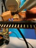
the Volume control wiper left pin has a signal, the right pin has no signal. Should it have a signal on right? (see the attached pic where I am probing)
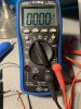
RE09 - 388k ohms
RE 21 - 0k - no continuity
RE 51 - 10k
RE 57 - 0k - no continuity(see pic)

IMG_5612.jpg IMG_9313.jpg
 
Did you check for signal at the above resistors? Should help localise the problem. The sucker bet is HE01.
One side of the volume control is normally connected to ground so no signal expected. Signal at middle pin/wiper is good.
 
Did you check for signal at the above resistors? Should help localise the problem. The sucker bet is HE01.
One side of the volume control is normally connected to ground so no signal expected. Signal at middle pin/wiper is good.

Checked for a signal. There is only a signal up to the left pin volume wiper and no signal in the center pin. Is the volume wiper faulty?

The rest of the resistors in the path show no signal.
 
There is only a signal up to the left pin volume wiper and no signal in the center pin. Is the volume wiper faulty?
Apologies, error on my part, the volume control has a fourth pin (for loudness).
Just for confirmation, there should be signal at the highlighted pins.
upload_2020-2-3_16-13-4.png
Since you found signal at the left pin you must have found the middle pin, no audio would point to faulty wiper contact.
You could try some of the magic spray. You could also resistance check between the left and wiper pins as highlighted
and compare with the front gang.
 
Apologies, error on my part, the volume control has a fourth pin (for loudness).
Just for confirmation, there should be signal at the highlighted pins.
View attachment 1751839
Since you found signal at the left pin you must have found the middle pin, no audio would point to faulty wiper contact.
You could try some of the magic spray. You could also resistance check between the left and wiper pins as highlighted
and compare with the front gang.

I Deoxit the wiper and it did not make a difference.
There is only signal at the highlighted pin second from the right(using the image you uploaded as a reference)
I double-checked the signal path and followed it from Pin7 to RE05 to the volume wiper and that's where it stops.
No signal at wiper pins on either front or back that connect to RE09 and RE10.
I compared the continuity of the solder points between the front wiper center pins that connect to RE09 and RE10 and found no issues with continuity.
 
There is only signal at the highlighted pin second from the right(using the image you uploaded as a reference)
This is the connection to Pin 7 which you previously flagged as OK

No signal at wiper pins on either front or back that connect to RE09 and RE10.
The front wiper and RE10 are for the right(?) channel, assume you feed sine wave into right channel otherwise I'm stumped...

I compared the continuity of the solder points between the front wiper center pins that connect to RE09 and RE10 and found no issues with continuity.
Not sure I understand but not a big deal. Would prefer to describe the volume pot as having an input pin (connection to pin 7)
and a wiper (middle pin) and a ground pin. Was asking to check continuity between the input pin and the wiper on the left
channel then repeat (EDIT: for the right channel) and compare the actual ohms, they should be about the same (+/-10%), would need to set volume on
about 3oclock (or whatever) position.

Need you to confirm no signal on front wiper when sine wave fed into right channel.
Also resistance between input pin and wiper for L&R channels is about the same
 
This is the connection to Pin 7 which you previously flagged as OK
Yes, that is correct.

The front wiper and RE10 are for the right(?) channel, assume you feed sine wave into right channel otherwise I'm stumped...

Yes, that is correct. Right channel.

Not sure I understand but not a big deal. Would prefer to describe the volume pot as having an input pin (connection to pin 7)
and a wiper (middle pin) and a ground pin. Was asking to check continuity between the input pin and the wiper on the left
channel then repeat (EDIT: for the right channel) and compare the actual ohms, they should be about the same (+/-10%), would need to set volume on
about 3oclock (or whatever) position.

Om resistance results:

Input pin 7 to Left input pin - 27k ohms
Input pin 7 to Left ground pin - 189k ohms

Input pin 8 to Right input pin - 29k ohms
input pin 8 to Right ground pin - 187k ohms

Need you to confirm no signal on front wiper when sine wave fed into right channel.

I am seeing a sinewave signal on both the left and right volume pot input pins.

Also resistance between input pin and wiper for L&R channels is about the same

Yes, they appear to be similar.
 
Om resistance results:

Input pin 7 to Left input pin - 27k ohms
Apologies for harping on this point but Pin 7 is connected to the vol input pin by a short circuit.
I'm sure you meant from pin 7 to wiper. I need to review the last couple of posts...
EDIT: You have audio/signal on one channel, correct?
 
Sorry for the "John & Betty" but we need to do it again.
Using sine wave input on L&R channels use oscilloscope to test at pins marked in red.
With amp powered off/unplugged, measure resistance between pins marked in green.
Repeat for pins marked blue, will need volume at normal listening 9oclock position.
I understand you have already done this but the results don't make sense (to me)
Reflow solder on all volume pins
upload_2020-2-4_19-1-0.png
 
Apologies for harping on this point but Pin 7 is connected to the vol input pin by a short circuit.
I'm sure you meant from pin 7 to wiper. I need to review the last couple of posts...
EDIT: You have audio/signal on one channel, correct?
Correct, I meant From pin 7 to wiper

Sorry for the "John & Betty" but we need to do it again.
Using sine wave input on L&R channels use oscilloscope to test at pins marked in red.
With amp powered off/unplugged, measure resistance between pins marked in green.
Repeat for pins marked blue, will need volume at normal listening 9oclock position.
I understand you have already done this but the results don't make sense (to me)
Reflow solder on all volume pins
View attachment 1752821

Sinewave Volume pins marked in red are showing a signal. The signal at RE09 and RE10 are also showing a signal but very faint in comparison to Volume pins. I am now hearing sinewave in left channel headphones when I raise the volume past 10 o'clock position. I also switched over to FM input and am getting faint and broken audio when the volume is raised past 12 o clock position. Looks like the volume potentiometer is faulty.

Here are the results after measuring pins marked in blue and green.
Blue - 48k ohms
Green - 46.6k ohms

I resoldered all the points to Volume wiper and did not hear a difference in sound output in headphones.
 
Back
Top Bottom