• The move to the new server is done. There are some software and database maintenance updates in process. This has us passing the hat around to help out. We appreciate any donations. Seriously, even a dollar helps. The payment page may be found here - https://www.audiokarma.org/support.html

Marantz 2325 Left Channel Pre Has No Output

Looks like the power amp boards are good. MBZ is much better than I am at diagnostics. I’ll bet he will be able to help you track down where the missing link is in the preamp signal.

 
just observations .it worked before so it should work now . one channel is working so maybe compare one to other with the scope following the signal paths .
i confess i use a damp finger to inject a signal and listen to the speakers as it is quicker that way for me . :D
 
  • Like
Reactions: mbz
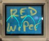
Input to Vol pot (pink/light blue) and wiper (red/blue) basically the same.
Pre-out Left is significantly lower than right, so problem between left
wiper and left pre-out. However it would be nice to verify power amp
as suggested.


Below are some more test points, the idea is to work through the audio path
and make comparisons between L&R channel to work out where it goes pear shapped.
Points with same colour should have same size waveform.

RED RE09/10
PINK HE01, 02 output pin 6
BLUE RE21, 22
YELLOW RE57, 58 after switch
Lt GREEN PE01 connector Pin 13, 14

Suggest work from bottom up, start at pin 13, 14, if they are ok then no need
to check further back

View attachment 1757455

EDIT: Work both the Hi and Lo filtyer switches a few times, any improvement on left waveform?

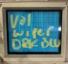
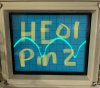
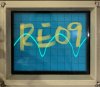
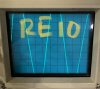
Working backward I'm seeing NO sine wave on LEFT until I reach RE09/10. The LEFT signal is lost at HE01 Pin 6. I also worked Hi-Lo switches and no change.

IMG_3674.jpg IMG_3673.jpg
 
Last edited:
Need to confirm the inputs (signal, power) to HE01 are ok, if so then HE01 suspect.

Check waveform at RED marks HE01 input pin 2 and HE02 pin 2 for comparison.
Check dc voltage at pin 7 (again, intermittent?) at green marks, 34Vdc expected.

With amp powered off measure resistance across RE17 (5.1k).
Check CE13 (3.3uf/35V Wima next to HE02), looks larger than CE14
upload_2020-2-10_6-6-17.png
 
Need to confirm the inputs (signal, power) to HE01 are ok, if so then HE01 suspect.

Check waveform at RED marks HE01 input pin 2 and HE02 pin 2 for comparison.
Check dc voltage at pin 7 (again, intermittent?) at green marks, 34Vdc expected.

With amp powered off measure resistance across RE17 (5.1k).
Check CE13 (3.3uf/35V Wima next to HE02), looks larger than CE14
View attachment 1758440


RED marked CE05/CE06 waveform present and equal.
HE01/HE02 Pin 2 waveform present and equal.
HE01 Pin 7 - 33VDC holding steady
HE03 Pin 7 - 33VDC holding steady
Green marked resistors - fluctuating between 33-34VDC
RE17 - 5.1k Ohms
CE13/CE14 - 3.3uf/50V WILMA
 
Points to HE01 (BA312) as being suspect faulty. Need one of the Marantz specialists to chime in with
latest on replacement options. Items on the bay likely to be fakes, also there is a replacement item, engineered at
a high price. What is the main purpose of the IC? it does provide some gain, any datasheet available?
 
Points to HE01 (BA312) as being suspect faulty. Need one of the Marantz specialists to chime in with
latest on replacement options. Items on the bay likely to be fakes, also there is a replacement item, engineered at
a high price. What is the main purpose of the IC? it does provide some gain, any datasheet available?

I have had an ongoing problem with the left channel for over a year and multiple trips to the repair shop could not resolve it. After reading other AK member reviews I decided to replace both BA312 with the Sparkos Labs BA312-M. I will circle back and give you an update once I install them.

Thank you so much MBZ for your guidance and persistence in identifying the problem.
You are one of AK's best! By the way MBZ, what's your name?
 
By the way MBZ, what's your name?
Mike, mbz nothing to do with mercedes benz, kind of an acronym for my name...

I decided to replace both BA312 with the Sparkos Labs BA312-M.
Yeah, I saw this site, wasn't really keen on the idea. BA312 equivalent circuit was 3 transistors and 4 resistors, the sparko
kit has "dozens" of parts...are they trying to justify the steep price? On the other hand, if it gives the performance improvement
they say, it would be a cheap investment.

Once you sort out the PE01 board I think you should have the power amp looked at by one of the AK Marantz techs.
I was a little concerned about the smoking and clipping you mentioned earlier
 
Mike, mbz nothing to do with mercedes benz, kind of an acronym for my name...


Yeah, I saw this site, wasn't really keen on the idea. BA312 equivalent circuit was 3 transistors and 4 resistors, the sparko
kit has "dozens" of parts...are they trying to justify the steep price? On the other hand, if it gives the performance improvement
they say, it would be a cheap investment.

Once you sort out the PE01 board I think you should have the power amp looked at by one of the AK Marantz techs.
I was a little concerned about the smoking and clipping you mentioned earlier

Mike, mbz nothing to do with mercedes benz, kind of an acronym for my name...


Yeah, I saw this site, wasn't really keen on the idea. BA312 equivalent circuit was 3 transistors and 4 resistors, the sparko
kit has "dozens" of parts...are they trying to justify the steep price? On the other hand, if it gives the performance improvement
they say, it would be a cheap investment.

Once you sort out the PE01 board I think you should have the power amp looked at by one of the AK Marantz techs.
I was a little concerned about the smoking and clipping you mentioned earlier


Mike,
I replaced the BA312's with Sparkos Labs BA312-M's and have a faint signal on the left side. I checked the audio path and the sine wave signal level is lost by 80% at the LEFT Volume wiper. The right volume wiper is working perfectly in comparison. I removed the volume wiper and used DeoxIT D100L to clean and DeoxIT lube the LEFT volume wiper to make sure it's making good contact. I'm moving the balance fader to the left 80% in order to hear audio evenly. I double-checked solder points and the audio path as you suggested earlier in this thread. It appears as though the left Volume wiper is faulty. Any suggestions for an alternative replacement for the volume wiper?

Audio path I checked
RED RE09/10
PINK HE01, 02 output pin 6
BLUE RE21, 22
YELLOW RE57, 58 after switch
Lt GREEN PE01 connector Pin 13, 14
 
Appears that the wiper is intermittent giving the conflicting test results.
I would (initially) resist the temptation to buy the ebay item that seems to be a perfect match. Try to find
a quality item and adapt from there. 4 pin pots are harder to find not to mention finding the wanted shaft
length etc... Maybe wait for the marantz gurus to chime in, they will have been through this already. I
will do a search later in the day
 
Some candidates from mouser
RV122F-20-15F-A50K-0072
652-PDB182-K220K503A

You will need to carefully check the datasheets against the wanted attributes, ie, 50K, A/audio/log taper, shaft length,
diameter, knurl length/type etc... do not rely on the mouser graphic, need to decode manufacturers part number.
Saw a nice blue alps type but lost the link. Most will be 3 pin so you may loose the variable loudness function.
You may need to tie the unused pin to GND, again the techs will chime in.
 
Appears that the wiper is intermittent giving the conflicting test results.
I would (initially) resist the temptation to buy the ebay item that seems to be a perfect match. Try to find
a quality item and adapt from there. 4 pin pots are harder to find not to mention finding the wanted shaft
length etc... Maybe wait for the marantz gurus to chime in, they will have been through this already. I
will do a search later in the day

UPDATE:
I have another 2325 waiting to be recapped and removed the Volume wiper from its tone board. I installed it on the PE01 we are currently troubleshooting and am seeing the same sine wave results from the LEFT side as noted in POST 50. It now appears Volume wiper is not the problem. Are there any resistors I should measure prior to the volume wiper? Would RE05/RE06 have any impact on the volume wiper? Both RE05/RE06 sine waves look even. Also, I disconnected the right amp and the burning smell is not present. Is there a possibility I am overdriving the right amp(bias is off) and in turn, it's affecting PE01?
 
RE05/RE06 are OK so need to look after this point. Audio path is then RE09, CE05, HE01-pin 2/input and HE01-pin 6/output. Need to check the feedback path CE11 and RE17(check this). I would check bias and set. Maybe try some
freeze spray on the abobe RE's and CE's, only a short spray. Don't see the right power amp causing this but it might
be time to have a look at what's getting hot. Only use low volume, 9o'clock position, the 2325 is something of a beast
 
RE05/RE06 are OK so need to look after this point. Audio path is then RE09, CE05, HE01-pin 2/input and HE01-pin 6/output. Need to check the feedback path CE11 and RE17(check this). I would check bias and set. Maybe try some
freeze spray on the abobe RE's and CE's, only a short spray. Don't see the right power amp causing this but it might
be time to have a look at what's getting hot. Only use low volume, 9o'clock position, the 2325 is something of a beast

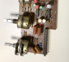
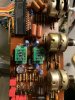
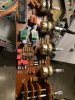
I swapped the tone board from my other 2325 to the unit we are testing and the unit ran perfectly with no overheating or smoke smell. I double-checked power supply is at 35VDC and biased both left and right amps. It's obvious the tone board I have been troubleshooting is causing issues with the rest of the unit. I'm attaching a pic of PE01 with Sparkos Labs BA312-M's.

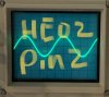
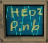
I checked the Audio path. The loss of signal continues to be at the volume wiper marked in RED(post #32). I also tried freeze spray in the RE and CE's in the audio path with no changes to the sine wave signal. Sine wave signal pics attached. I had to raise the volume to 12 o'clock to register a sine wave signal on the LEFT side. Anything below 12 o'clock does not show up on the oscilloscope.


Oo'clockIMG_3727.jpg IMG_3732.jpg IMG_3728.jpg IMG_3731.jpg IMG_3730.jpg IMG_3729.jpg IMG_3733.jpg IMG_3736.jpg IMG_3737.jpg t
 
I have another 2325 waiting to be recapped and removed the Volume wiper from its tone board. I installed it on the PE01 we are currently troubleshooting and am seeing the same sine wave results from the LEFT side as noted in POST 50. It now appears Volume wiper is not the problem.
CE09 shorting to GND? Need to review, has it been replaced/inserted correctly?
 
Measure resistance between points in yellow, should be open. Give this area a clean with acetone or circuit
board cleaner (acetone will damage plastic) and post an updated pix.
upload_2020-2-21_19-11-57.png
 
Measure resistance between points in yellow, should be open. Give this area a clean with acetone or circuit
board cleaner (acetone will damage plastic) and post an updated pix.
View attachment 1771039
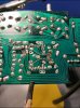

I cleaned up this area and double-checked the solder points. The Sparkos Labs BA312-M's MOD requires the removal of several components in this area so I can't measure the resistance between the two points in yellow. I also had to take two separate cap leads and solder it on the other side of the track(see pic) because of missing copper track. I also measured the sinewave signal at HE01/HE02(see pic).

IMG_4BEE2F905E91-1.jpeg
IMG_3751.jpg
IMG_3750.jpg
IMG_3758.jpg
IMG_3759.jpg
 
The Sparkos Labs BA312-M's MOD requires the removal of several components in this area so I can't measure the resistance between the two points in yellow
Not sure I understand. One meter probe on one solder blob, other probe on other blob, amp powered off/unplugged.
Looking for a low resistance path to GND that's killing the audio on that channel.

I resoldered CE09 and GND. No change to the sinewave signal.
Speculating that CE09 was leaking to GND, however it appears new, possibly replace to rule it out as suspect.
 
Back
Top Bottom