• The move to the new server is done. There are some software and database maintenance updates in process. This has us passing the hat around to help out. We appreciate any donations. Seriously, even a dollar helps. The payment page may be found here - https://www.audiokarma.org/support.html

Marantz 2325 Left Channel Pre Has No Output

The signal at RE09 and RE10 are also showing a signal but very faint in comparison to Volume pins.
The volume control is wired up as an attenuator. "Full strength" audio is received from the source and the volume control
will give you from 0% to 100%. The input pin will have the full strength audio and the wiper will have the 0%-100% depending
on how much you turn it up. So it's not unexpected that the RE09 and RE10 are much lower than the input pin/Pin 7,8

Resistance measurements between vol input and wiper look ok.

The volume pot is probably ok, you may have a gain issue which came about after recapping PE01 board.
If sinewave at RE09 and RE10 are about the same level then possibly a power supply issue to HE01 & HE02, measure
dc voltage at pin 10, expect about 35Vdc
 
The volume control is wired up as an attenuator. "Full strength" audio is received from the source and the volume control
will give you from 0% to 100%. The input pin will have the full strength audio and the wiper will have the 0%-100% depending
on how much you turn it up. So it's not unexpected that the RE09 and RE10 are much lower than the input pin/Pin 7,8

Resistance measurements between vol input and wiper look ok.

Thank you for the explanation. I read an AK thread discussion on how to clean and lube a wiper. What are your thoughts on this?

https://audiokarma.org/forums/index.php?threads/replacing-bad-volume-pot-choices.779545/page-2

The volume pot is probably ok, you may have a gain issue which came about after recapping PE01 board.
If sinewave at RE09 and RE10 are about the same level then possibly a power supply issue to HE01 & HE02, measure
dc voltage at pin 10, expect about 35Vdc

There are only 7 pins on HE01 and HE 02(see pic). Schematic reads pin 7 should measure 34v.
Results
HE01 - 24v
HE02 - 23v

IMG_3434430BA6F3-1.jpeg
 
I don't have the BA312 datasheet, while 23-24V does not sound unreasonable a google on AK shows most are in that
33-34V range so maybe a closer look at that supply is needed. Both channels should be somewhat quiet and the same level.

Measure Vdc at pin 10 on the PE01 board, expect about 35V, in this case measure volt drop across RE73(100) then
measure RE73 resistance, in circuit ok but amp must be powered off, calculate current from volt drop and measure
resistance, expect 5mA max.

If Pin 10 is low (less than 30V) then check power supply.
Measure H802 and H803 b/c/e voltages to GND.
In the past, did you ever set the regulated voltage as per the service manual?
upload_2020-2-6_8-34-11.png

If RE73 current is about 5mA try the above voltage adjustment
 
I don't have the BA312 datasheet, while 23-24V does not sound unreasonable a google on AK shows most are in that
33-34V range so maybe a closer look at that supply is needed. Both channels should be somewhat quiet and the same level.

Measure Vdc at pin 10 on the PE01 board, expect about 35V, in this case measure volt drop across RE73(100) then
measure RE73 resistance, in circuit ok but amp must be powered off, calculate current from volt drop and measure
resistance, expect 5mA max.

Measurements
Pin 10 - 35.31 VDC
RE73 - 35.31 VDC
RE73 - Resistance 97.4 ohms


I = Amps
V= 35.31 VDC (RE73)
R = 97.4 Resistance (RE73)

V/R = .36Amps(I)

E = Voltage Drop
E = I * R
E(35.064VDC) = I(.36) * R(97.4)


If Pin 10 is low (less than 30V) then check power supply.
Measure H802 and H803 b/c/e voltages to GND.
In the past, did you ever set the regulated voltage as per the service manual?

Yes. I set the regulated voltage per service manual to 35VDC when I recapped P800.

View attachment 1754356

If RE73 current is about 5mA try the above voltage adjustment
 
Measurements
Pin 10 - 35.31 VDC
RE73 - 35.31 VDC
RE73 - Resistance 97.4 ohms


I = Amps
V= 35.31 VDC (RE73)
R = 97.4 Resistance (RE73)

V/R = .36Amps(I)
The idea was to measure the volt drop across RE73, ie red probe on one pin, black probe on the other pin of RE73.
With Pin 10 at 35.31 and pin 7 of HE01 at 24V give 11.3Volts/100ohms= 110mA though need to allow for RE69 and others.

The repair marked in green is in play, check for solid contact ie, not
intermittent. Check no continuity/short between green and yellow marked solder blobs.
CE39 solder (red) looks a bit ordinary, probably just the pic. Likewise the 2 blobs
marked in blue, should not be any contact, check for any specks etc between the blobs.
Check RE74, zero ohm resistor, I assume this is just a joining link?
upload_2020-2-6_19-35-27.png
 
The idea was to measure the volt drop across RE73, ie red probe on one pin, black probe on the other pin of RE73.
With Pin 10 at 35.31 and pin 7 of HE01 at 24V give 11.3Volts/100ohms= 110mA though need to allow for RE69 and others.

The repair marked in green is in play, check for solid contact ie, not
intermittent. Check no continuity/short between green and yellow marked solder blobs.
CE39 solder (red) looks a bit ordinary, probably just the pic. Likewise the 2 blobs
marked in blue, should not be any contact, check for any specks etc between the blobs.
Check RE74, zero ohm resistor, I assume this is just a joining link?
View attachment 1754850


I was getting intermittent contacts in green so I resoldered them.

NO continuity shorts between yellow and green

Resoldered CE39 and checked for continuity

Two blobs in blue are not visually making any contact and double-check for continuity.

Checked resistor RE74 contact points and resoldered them. I also checked resistance and measures .05

Still no sound or signal on left side.
 
There should be a track (in red) between the 2 blobs, maybe intermittent/bad contact. Check resistance
between the blobs
upload_2020-2-7_6-18-51.png

EDIT: Remeasure dc voltage at pin 7 of HE01, repeat for HE02. Previously reported 23-24V.
34V expected.
 
Last edited:
There should be a track (in red) between the 2 blobs, maybe intermittent/bad contact. Check resistance
between the blobs
View attachment 1755158

EDIT: Remeasure dc voltage at pin 7 of HE01, repeat for HE02. Previously reported 23-24V.
34V expected.

Contact was intermittent for two blobs in red. I resoldered and the track is now making better contact. No change in left channel sound.

Remeasure results

HE01 Pin 7 - 34 VDC
HE02 PIN 7 - 34VDC

I am using a VARIC and must have not had it turned to 120V (my apologies)
 
Just a refresh.
Were both channels working ok before the recap?
What is the situation? left or both channels very quiet?

Set volume to quite loud eg, 3oclock position, no speakers/headphone connected.
Sine wave input to L&R channels. Note the signal "strength"/amplitude at left channel
volume wiper or RE09. Compare with RE21 (zero ohms). Repeat for right channel vol
wiper or RE10 and RE22(zero ohms).

Sine wave at RE21 >= RE09?
RE22 >=RE10?

iphone/pod plugged into MAIN-IN RCAs has normal volume?


Also check audio level at Pin 13(L) and 14(R) and compare with above

Everything was working fine prior to recapping Preamp, I have done the following:
  1. Recapped the P800 and set to 35VDC
  2. Recapped L/R P700 including all heatsink transistors and Biased both amps.
I set the volume of the sine wave to 1 o'clock position. I could not turn it up higher because the power supply protection relay would start clicking and I smelled something electrical burning. I connected to DIM Bulb tester and raised volume. Bulb got really bright when I reached 3 Ocolock volume position but stayed mildly lit when keeping volume under 1 o'clock volume position. I switched over to FM radio and was able to raise volume 100 percent without protection relay engaging. I am still smelling burning in the general area of the power supply P800.

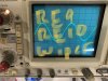
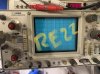
During the sine wave testing of left and right channels, I noticed sine wave changes primarily in the Vol wiper middle pins.
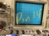
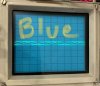
See photos of sinewave results on the oscilloscope.
IMG_3635.jpg


This is where the sinewave strength changed
IMG_3636.jpg


The remaining sine wave was not consistent.
IMG_3640.jpg IMG_3637.jpg IMG_3638.jpg IMG_3639.jpg
 
I set the volume of the sine wave to 1 o'clock position. I could not turn it up higher because the power supply protection relay would start clicking and I smelled something electrical burning. I connected to DIM Bulb tester and raised volume. Bulb got really bright when I reached 3 Ocolock volume position
OK, "we" are pushing the amp too hard, there are probably other issues, best not get distracted.

The good news is that HE01, HE02 along with HE03,4,5,6 are probably working, hard to tell with the clipping, maybe repeat the test
at more reasonable listening levels 9 o'clock?

Below, the vol pot inputs are marked in pink and light blue. Wipers are red and blue, RE09, RE10 test points are yellow and green.
The wiper waveform will be smaller than the input. The wiper and RE09/RE10 waves should be the same. You can either
test/probe the wiper pin (before it goes through the PCB) or the solder blob, a difference would point to bad solder connection.
A difference between the wiper and RE09/RE10 test points would point to a bad track
upload_2020-2-7_18-59-16.png
 
OK, "we" are pushing the amp too hard, there are probably other issues, best not get distracted.

The good news is that HE01, HE02 along with HE03,4,5,6 are probably working, hard to tell with the clipping, maybe repeat the test
at more reasonable listening levels 9 o'clock?

Below, the vol pot inputs are marked in pink and light blue. Wipers are red and blue, RE09, RE10 test points are yellow and green.
The wiper waveform will be smaller than the input. The wiper and RE09/RE10 waves should be the same. You can either
test/probe the wiper pin (before it goes through the PCB) or the solder blob, a difference would point to bad solder connection.
A difference between the wiper and RE09/RE10 test points would point to a bad track
View attachment 1755735


The waveform is identical between red/blue and green/yellow. I also checked solder blob contacts to make sure there was no difference in the waveform.
 
Both channels appear to be outputting equal signal, the question is, is it the correct level or very quiet at this point.
The vol pot is probably a log taper, with volume set to 3oclock (25%) it might be outputting about 10% volume, maybe higher.
Check waveform at input pins pink/red, light blue/blue, expect the wipers to be about 10%. You can calculate actual value
by measuring resistance between input and wiper (pink, red) and then between input and GND (pink, pin above yellow) and
express as a percentage, repeat for other channel.

Suggest check levels at the PRE-OUT RCA's, just insert probe. Level should be greater than level at wipers.
Also with vol at 3oclock what is the peak-peak waveform at the speakers
 
Should also check connector/solder joints/wires to PE01 board.
Checking sinewave at PRE-OUT RCA's and verifying power amp by feeding low level supply into MAIN-IN
would also be helpful
 
Both channels appear to be outputting equal signal, the question is, is it the correct level or very quiet at this point.
The vol pot is probably a log taper, with volume set to 3oclock (25%) it might be outputting about 10% volume, maybe higher.
Check waveform at input pins pink/red, light blue/blue, expect the wipers to be about 10%. You can calculate actual value
by measuring resistance between input and wiper (pink, red) and then between input and GND (pink, pin above yellow) and
express as a percentage, repeat for other channel.

Suggest check levels at the PRE-OUT RCA's, just insert probe. Level should be greater than level at wipers.
Also with vol at 3oclock what is the peak-peak waveform at the speakers


Resistance Results :

Pink - 19.5k ohms
Red - 10.22k ohms
Ground - 4.6 ohms

Light Blue - 19.73k ohms
Blue - 10.97k ohms
Ground 25.4 ohms

See pics of Sinewave results with volume at 9 o'clock (25% volume).
 

Attachments

  • IMG_3651.jpg
    IMG_3651.jpg
    59.5 KB · Views: 3
  • IMG_3656.jpg
    IMG_3656.jpg
    65 KB · Views: 3
  • IMG_3657.jpg
    IMG_3657.jpg
    55 KB · Views: 3
  • IMG_3654.jpg
    IMG_3654.jpg
    60.9 KB · Views: 3
  • IMG_3655.jpg
    IMG_3655.jpg
    62.9 KB · Views: 3
  • IMG_3652.jpg
    IMG_3652.jpg
    61.3 KB · Views: 3
  • IMG_3653.jpg
    IMG_3653.jpg
    60.3 KB · Views: 3
  • IMG_3650.jpg
    IMG_3650.jpg
    57.1 KB · Views: 3
Should also check connector/solder joints/wires to PE01 board.
Checking sinewave at PRE-OUT RCA's and verifying power amp by feeding low level supply into MAIN-IN
would also be helpful

Solder on wires from power supply to preamp looks like its making good contact. Connector wires to preamp appear to be fine and not loose. See pics.IMG_3665.jpg IMG_3664.jpg

Regarding MAIN-IN, I need to clarify connections.
1. Feed Sinewave signal into MAIN-IN
2. Check sinewave signal at PRE-OUT
 
  • Like
Reactions: mbz
Input to Vol pot (pink/light blue) and wiper (red/blue) basically the same.
Pre-out Left is significantly lower than right, so problem between left
wiper and left pre-out. However it would be nice to verify power amp
as suggested.
Feed sine wave into main in. Check sine wave signal at speaker terminals.

Below are some more test points, the idea is to work through the audio path
and make comparisons between L&R channel to work out where it goes pear shapped.
Points with same colour should have same size waveform.

RED RE09/10
PINK HE01, 02 output pin 6
BLUE RE21, 22
YELLOW RE57, 58 after switch
Lt GREEN PE01 connector Pin 13, 14

Suggest work from bottom up, start at pin 13, 14, if they are ok then no need
to check further back

upload_2020-2-9_10-3-14.png

EDIT: Work both the Hi and Lo filtyer switches a few times, any improvement on left waveform?
 
Back
Top Bottom