• The move to the new server is done. There are some software and database maintenance updates in process. This has us passing the hat around to help out. We appreciate any donations. Seriously, even a dollar helps. The payment page may be found here - https://www.audiokarma.org/support.html

Marantz Model 9 Prototype

How was the original Marantz logo imprinted? Just curious because I've had a few pieces over the years with various markings wiped off due to age.

I also know they make high grade "decals" but I clearly am not familiar with how these units were dressed.

What would you recommend for redoing the lettering? Just out of curiosity.

Airtime, this is a museum piece, all MUST be kept original. This was hand built by Sid Smith himself. This isn't a piece you fiddle with, Bryans12 knows that.
If this was a run of the mill Model 9, (those words connected don't seem right:)) then the black anodized handle on the removable front plate would be engraved with "Marantz".
The other lettering is just silk-screened on the faceplate... unlike this one, which looks engraved and paint-filled, similar to other latter model first production runs (like the 22xx stuff)

I have some reproduction Dial-glasses that I had done through RadioDaze, and they did a great job on those, I would recommend them for anything. However if you look around, their is probably a shop close to you that might re-screen a chassis for you. I have a guy near me that prints up these transfer-decals that look identical to silk-screening. He can replicate any font, size, logo or whatever. He can't be the only one.
 
How was the original Marantz logo imprinted? Just curious because I've had a few pieces over the years with various markings wiped off due to age.

I also know they make high grade "decals" but I clearly am not familiar with how these units were dressed.

What would you recommend for redoing the lettering? Just out of curiosity.


Airtime, I would start a new thread with your question to keep this one on topic.

The marks on this unit have not worn off. There wasn't one there to begin with. Your question is impossible to answer without knowing which model you are referring to. Start a new thread and it will get more exposure ensuring you find the info you need.

Good luck,

Bryan-
 
Agreed that this is a museum piece that should remain untouched. All Marantz Model 9's with the standard non rack mount faceplate have engraved lettering. The font is different on this prototype though...
 
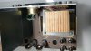
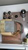
Bryans -- Based on the circuit I can determine from the pics provided, I too would strongly suggest that this is a prototype/development unit. Using the closeup pic of the underside showing the four 9 pin miniature tubes, the tube at the bottom left would constitute the standard phase reverse/AF amplifier stages as used in the production design, and would be a 6DJ8 tube.

The bottom right tube is -- I believe -- the mystery tube, but this needs clarification if you would, please. In the first set of uncleaned pics, this socket (being the front right corner tube) -- again, I believe -- shows the mystery tube installed in that location, while the second 6DJ8 is installed in the back inner socket of the top side pics. However, in your pics later detailing the mystery tube, you show it installed and its location as being in the back inner socket. I believe this is in error.

The circuit of this four tuber (as based on the underside shots) supports the idea that the mystery tube in fact is installed in the front right corner position (bottom right socket of the underside close up), and based on the circuit and appearance of the tube, is very likely a 12AU7 or useful variant.

It appears that in this unit, the phase inverter action has been divided between two tubes: the mystery tube in the bottom right socket, and the second 6DJ8 of the top left socket. The tube in the top right socket is the standard 6CG7 CF driver tube.

Assuming that the bottom right tube is the mystery tube, its configuration is rather unique, with one section being actively driven via direct coupling into it from the previous AF amplifier stage, and the other section being configured for grounded grid operation. However, both sections are configured as CF stages. The CF outputs of the mystery stage then drive the CC current portion of the inverter, being the second 6DJ8.

The advantage of this configuration is that the grid circuit impedance of the CC section is made to be identical, which would no doubt allow the output of the inverter to maintain a balanced output at higher frequencies than would be possible without splitting up the grounded grid and CC functions (as with the traditional diff-pair inverter used in the production units). As to how much improvement the additional stage provides, it is likely academic since the HF response of the overall design must be rolled off anyway to achieve good HF stability. And clearly, it didn't make the production cut. However, in the ever greater effort to make the design have as much performance as the engineering capability of the day would allow, its just one step closer to perfection.

Congrats on finding and saving what is no doubt a very unique piece of audio history!

Dave

 
Last edited:
Bryans -- Based on the circuit I can determine from the pics provided, I too would strongly suggest that this is a prototype/development unit. Using the closeup pic of the underside showing the four 9 pin miniature tubes, the tube at the bottom left would constitute the standard phase reverse/AF amplifier stages as used in the production design, and would be a 6DJ8 tube.

The bottom right tube is -- I believe -- the mystery tube, but this needs clarification if you would, please. In the first set of uncleaned pics, this socket (being the front right corner tube) -- again, I believe -- shows the mystery tube installed in that location, while the second 6DJ8 is installed in the back inner socket of the top side pics. However, in your pics later detailing the mystery tube, you show it installed and its location as being in the back inner socket. I believe this is in error.

The circuit of this four tuber (as based on the underside shots) supports the idea that the mystery tube in fact is installed in the front right corner position (bottom right socket of the underside close up), and based on the circuit and appearance of the tube, is very likely a 12AU7 or useful variant.

It appears that in this unit, the phase inverter action has been divided between two tubes: the mystery tube in the bottom right socket, and the second 6DJ8 of the top left socket. The tube in the top right socket is the standard 6CG7 CF driver tube.

Assuming that the bottom right tube is the mystery tube, its configuration is rather unique, with one section being actively driven via direct coupling into from the previous AF amplifier stage, and the other section being configured for grounded grid operation. However, both sections are configured as CF stages. The CF outputs of the mystery stage then drive the CC current portion of the inverter, being the second 6DJ8.

The advantage of this configuration is that the grid circuit impedance of the CC section is made to be identical, which would no doubt allow the output of the inverter to maintain a balanced output at higher frequencies than would be possible without splitting up the grounded grid and CC functions (as with the traditional diff-pair inverter used in the production units). As to how much improvement the additional stage provides, it is likely academic since the HF response of the overall design must be rolled off anyway to achieve good HF stability. And clearly, it didn't make the production cut. However, in the ever greater effort to make the design have as much performance as the engineering capability of the day would allow, its just one step closer to perfection.

Congrats on finding and saving what is no doubt a very unique piece of audio history!

Dave


Dave, Thank you so much for your input! You've caught something I missed here and now I hate myself for it. I'll explain why..

I just looked back at the first couple pictures I took and realize I must of rubbed the info off the tube while cleaning it. :(

Here's the first shot. The mystery tube belongs on the outer corner, the spot that's missing on the others.

Screenshot_2016-08-28-16-30-49.png
 
OK. So my assumption was correct as to which socket the mystery tube really belongs in? That's good, as the circuit design supports it being in the front corner position as well. As for the mystery tube itself, while it would be difficult to determine the specific version other than by the markings remaining on the tube, it could easily be verified as to what family it belongs to by anyone who has and is familiar with a curve tracer. Again, I strongly suspect it is from the 12AU7 family. That would match not only its physical appearance, but also that tube's ratings/characteristics versus the needs of the stage it is operating in.

Dave
 
Interesting. Now that I've read back through some of the thread (since I came in late), it's interesting to note the comments on Sid trying different OPTs in the development phase of the 9, versus my comments that the extra tube would (basically) help to ensure an extended and balanced HF response from the inverter stage. The extra tube would definitely go hand in hand with the testing of HF characteristics that the different transformer examples might display.

Dave
 
The extra tube could have been used as an oscillator to generate a signal (perhaps 1 kHz) to balance the phase splitter.
On the Marantz 8B an external signal is needed.
The signal could be anything from 50 Hz to 1 kHz.
The final version of the Model 9 used an attenuated power line signal (60 Hz), so perhaps this eliminated the tube....
 
The wiring of the mystery tube socket as offered in the pics does not support that it is an oscillator, but of course being a development model, it could have been configured for many different purposes over the course of that adventure!

Dave
 
I wish you could evaluate and test the amplifier. I'm sure you would have this mystery solved!
Some things I noticed:
- The triode switch at the front. This proved to be problematic, since the design does not allow operation "on the fly". Hence it was put in the back under the cage for the production version. Being close to the tubes probably worked better as well.
- No trimmer capacitors in the feedback network. It may be using a single tertiary winding a la Marantz Model 8.
- No neon lamp in the input stages so it may not be direct coupled. Actually, the first production units lacked the neon lamp also. It appeared around SN 1500.
- No Zener diode.
 
The saga continues!

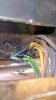
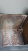
I did some more poking around this morning and found something crazy, one of the transformers was never potted?!?

I've never opened up a potted transformer so I really don't know what to look for. What's odd is that the wiring for both the potted and non potted are the same colors, guage, pattern etc. They clearly look the same.

I managed to have enough slack to tip the potted transformer up to confirm its potted (I can tell by tapping on the box also) but I wanted to be certain of the color scheme of wires coming out and that nothing had been cut or spliced.

Here it is.

20160829_090103.jpg

Now for the odd part. The left transformer is not potted and just laying in there. My first thought was that someone had at one point replaced it BUT the wires are identical to the other side and the cover has NO sign of any scraping which would've been evident if it had to be cleaned out, right?

Here's what I found.

20160829_090220.jpg

20160829_090306.jpg

20160829_090335.jpg

20160829_090409.jpg

20160829_090422.jpg

I feel like we're unraveling a some puzzle pieces here. Kind of feel like a detective.

Also, I've gottenthe date codes on the back of the RPW pots.

Looks like mid to late 59 and early 1960.

Week 6 of 1960.
20160829_085054.jpg
Week 37 of 1959.
20160829_085044.jpg
Another 5937.

20160829_085152.jpg

I'd imagine this is the production period of the switch as well.
20160829_085347.jpg
 
Last edited:
Pretty awesome- I don't find it unusual that the output has not be potted. They may have been experimenting and the transformer may have just come off the winding machine.. cool.
 
Dave, a question about the cathode follower g1 drive to the output tubes.
Do you think he did this to overcome Miller effect when the paralleled output 6CA7 beam tubes were run triode?
The 8B that followed the 9 still used a Mullard configuration of the 8 tho the 9 was more complex.
 
The saga continues!....

Thanks for those pictures! Man that output transformer is massive! No tiny transformer hidden under a large can like some other manufacturers did and still do!
The can may have been reused several times and the transformer wound in-house. The 1959 and 1960 date codes on the pots indicate the approximate date the prototype was put together. Development must have started early in 1959, coinciding with the introduction of the Model 7.
 
Last edited:
Dave, a question about the cathode follower g1 drive to the output tubes.
Do you think he did this to overcome Miller effect when the paralleled output 6CA7 beam tubes were run triode?
The 8B that followed the 9 still used a Mullard configuration of the 8 tho the 9 was more complex.

The Model 9 had indeed a more complex input stage. The input tube used as buffer was outside the global feedback network which was unusual. A popular mod in the 1970s was to bypass the first half of V1, which eliminated the gain control also. I don't know if this was really beneficial as the amplifier had very low distortion and high S/N ratio in stock form.
 
The Model 9 had indeed a more complex input stage. The input tube used as buffer was outside the global feedback network which was unusual. A popular mod in the 1970s was to bypass the first half of V1, which eliminated the gain control also. I don't know if this was really beneficial as the amplifier had very low distortion and high S/N ratio in stock form.
The input phase selector stage could be bypassed or eliminated entirely, and the function performed by a dpdt switch in the speaker line. That would leave the added cathode follower drive stage the main diff between the 8 and the 9 configuration.
Figuring out those function switches is another matter, my head hurts!
Dave's da man!
 
Last edited:
Back
Top Bottom