• The move to the new server is done. There are some software and database maintenance updates in process. This has us passing the hat around to help out. We appreciate any donations. Seriously, even a dollar helps. The payment page may be found here - https://www.audiokarma.org/support.html

Mass Loaded Transmission Line Speakers

Thanks, Jim!

I am hoping to find a poly-fil batt - I have pulled this from various OEM speakers over time, and I like how it stays in place better than the loose poly-fil. Hornresp is able to model poly-fil, but not foam. I am adding the eggcrate foam by the seat of my pants. Is that the type of foam you are calling low density polyurethane?

My first pair of speakers, I had gone a bit too large again on the terminus opening, and I measured a fair bit of higher frequencies (700-900Hz or so) coing out of the opening, so I adjusted it both for a bit better bass extension, and to reduce the leakage of the higher frequencies. On this second pair, I am filling the part of the TL that is getting reduced anyway, as well as those higher frequencies. Though the last vertical baffle on the second design is doing that latter part, as well. My best guess is that foam along the wall (in the direction of the TL, so to speak) only damps the flow, and at the bottom, it damps the reflection, without changing the effective length of the segment?

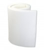
The egg crate is low density but no the exact type used to dampen the lines.
The Airtex regular density is the type Fried used.
14759583.html
Most fabric stores have large rolls and sell it by the foot.
14759583ALT1.jpg

I have yet to find any PC program that models foam in transmission lines.

Many like Fried knew from experience how to lay out the foam
The density behind the driver in the first section of the line was 60% decreasing to 15% in the last section of the line.

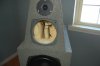
I enclosed a photo of how the foam is placed in the transmission line in one of my satellite speakers behind the 6.5" driver.

I have used a test cd with oscillated warble tones and a volt meter at the back of the speaker cup terminal input to measure the impedance.
This method seems outdated but is very accurate to find any impedance peaks.
 

Attachments

  • DSC_0123.JPG
    DSC_0123.JPG
    72.4 KB · Views: 35
Fried claimed he did give advice to Amar Bose when it came to the Wave Radio design.
IIRC there is a circuit to boost the bass in the wave radio design.

The Fried O1 and SM1 subwoofer designs were offset a little.
They were the wide less deep enclosure designs.
I don't have the plans on my computer.

I seriously doubt that Bose took advice from anyone, when I interviewed with them
in 1980 I told them to read my TL paper and pointed out the much lower measured
distortion at bass frequencies. They said we have something hot (to make them a
lot of money), and that was auto sound where they'd sell systems at the rate that
cars with high end sound were selling. Then quite a few years later, they did the
acoustic wave thing. It is interesting that none of the systems I've seen use any
damping, rather they use EQ to fix the resonances, very important for an undamped line.
 
I've built 3 big TLs of my own design, and none since my paper where my advisor
suggested just to build a big bass reflex. But, I do understand how they work and
my advice is to stuff the stub end up to half or 3/4 way down the line. But leave the
last 1/2 to 1/4 undamped or just with walls lined.
If the OP changes the damping, he could leave one as original and compare to
alternate stuffing with the other. Measurements are even better.

Too much damping will kill the output at port tuning and should be avoided. It may
be just fine the way it is.
 
I seriously doubt that Bose took advice from anyone, when I interviewed with them
in 1980 I told them to read my TL paper and pointed out the much lower measured
distortion at bass frequencies. They said we have something hot (to make them a
lot of money), and that was auto sound where they'd sell systems at the rate that
cars with high end sound were selling. Then quite a few years later, they did the
acoustic wave thing. It is interesting that none of the systems I've seen use any
damping, rather they use EQ to fix the resonances, very important for an undamped line.

I know that Fried knew many of his peers in the speaker industry from all the trade shows.
Those guys sure enjoyed talking to each other and explaining why their brand was the best to purchase.

The wave radio would sound horrible without any electronic equalization using an undamped line.

Pete is your TL paper on the internet?
I would enjoy reading it.

NeilBEN I always enjoy a thread about TL speakers and sharing info.
 
I know that Fried knew many of his peers in the speaker industry from all the trade shows.
Those guys sure enjoyed talking to each other and explaining why their brand was the best to purchase.

The wave radio would sound horrible without any electronic equalization using an undamped line.

Pete is your TL paper on the internet?
I would enjoy reading it.

NeilBEN I always enjoy a thread about TL speakers and sharing info.

No, it was hand typed around 1979, not even electronic format. I called the school library and
there's no trace of it LOL!

I have a paper copy of the G. S. Letts paper also, it is from the University of Sydney and over
there papers are written on legal sized paper. I don't think that any of my copiers will do legal.
I also have a copy of Richard Small's thesis and it is also printed on this larger almost legal size.
Nearly all of his thesis was published in his papers at the AES.

I've sent out the Olney paper on the net.
Here is the Olney paper where he refers to it as an acoustical labyrinth:
http://p10hifi.net/TLS/downloads/Acoustic-Labyrinth-Olney.pdf

Note that Olney was an RF design engineer and he provides TL equations and uses standing
wave measurements to measure acoustical impedance. I was a TA for a microwave lab where
we did the same thing in the electrical world. You measure VSWR to compute impedance and
it is completely analogous for an acoustical TL. Many of the articles on TLs in the 60s and 70s
were not even close to providing this level of detail.
 
Last edited:
Yes the cone movement is reduced at the tuning frequency but about off the tuning frequency. Just look at the impedance curve. You still have timing distortion and you still have much higher distortion that todays well designed critically damped woofer enclosure systems don't have. And AR 1W had about 6 % distortion back in the 50's, Mcintosh ML series woofers had less tha 3% at 30 Hz in the early 70's. B&O had some speakers in the 70's that had less than 2 % distortion when every one else making point source speakers were more than 3 times that much. Line arrays really reduced distortion below 1% which a lot of speakers today can't match. Even JBL's DD 67000 has distortion and using the magnetic shorting rings that Mcintosh developed in the 80's. Magico uses the technology too to get less than 2% from their sealed woofers systems. Yes porting reduces distortions in some areas but there are other issues created that deter from proper reproduction. All speakers are compromises, you just have to choose which you can tolerate and which ones you reject.

What impedance curve?
 
I've always heard the issue with these designs is the delay at the port making the group delay bad and imparting a looseness to the sound as the timing is off. Do you experience any of that and what are your feelings about it? There are trade offs to everything in life.

The clarity and tightness of this speaker is better than anything I have heard in the 40+ years I have been seriously listening to music. Bass is the hardest thing to get right - and this speaker come the closest to "right" of anything I have heard. It is hard to pin down the sound or character of the speaker - because the character of each recording is what is obvious.
 
Right go ahead and put words in his mouth, lol!
What I would say is that poorly designed (high tuned) bass-reflex or vented designs suck.
But try out the PSB Stratus Golds and you'll hear vented that sounds like a TL.
Or try Genesis 2 s that are also tuned very low.

The Linaeum Model 10 that is linked earlier in this thread is tuned to 32 Hz
also very low and got an excellent review, see Fig 1 for port tuning:
https://www.stereophile.com/content/linaeum-model-10-center-channel-loudspeakers-measurements
 
Last edited:
So what you are saying is that bass-reflex designs suck?
No.

What I am saying is the TL designs can have several advantages. They seem to combine the precision of open baffle, because the woofer is operating in a lower pressure cabinet - and it is much smaller than many OB. A larger woofer is always going to have more mass. The two drivers I have used so far, are 25gm and 27.2gm Mms, and the next ones I want to try are 19.8gm. The clarity in the bass, and everywhere else, is amazing.

These speakers are going to my brother - he has been helping me do major construction on my house for years. But I will be building several more pairs. These are my ultimate speaker.

And on the low end, having the mass loading etc, gives you far more extension from a given driver size, than even ported designs. See the recommended tuning for this SB Acoustics woofer, that I posted above.

I had the FFT window running in REW this evening, and the Hans Zimmer track from The Dark Knight called "Why So Serious", and it has a lot of bass at 38Hz, 36Hz and 32Hz - and 19.3Hz. That lowest stuff is not as loud as the 30Hz range, but it was on par with the 60-100Hz region. That might be the speakers, or it may be the recording. But getting usable response that low is icing on the cake. From two 8" woofers.

As we have discussed on the thread already - there is a lot of overlap in designs, and sometimes things are using elements that make them hard to call one type of design, or another. There are no hard and fast rules, that make one thing always great, and something else always terrible.
 
During the COVID shutdown I enjoyed building these MLTLs from Martin King's online plans. Used 3/4 MDF and believe me they are hernia heavy. Amazing bass from an 8" single full range driver. In this build I had to sew up a cheese cloth sleeve containing poly-fil and suspend it half way up the enclosure. I've become a new fan of MLTL speakers. At 98 dbs these are SET friendly.

P1010015.jpeg
 
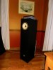
Anybody can make whatever type of speakers they want to. Traditionally, transmission lines are much more difficult, and they required a lot more effort beforehand, and a lot of trial and error. Obviously, there are not all that many transmission line speakers out there. I had the once in a lifetime good luck to find the pair of Linaeum LT1000 speakers on eBay for $400. They were at a pawn shop in Danbury CT, and had to be picked up - I live about 4 hours drive from there. I picked them up literally on the last weekend before the pandemic shut things down.

Connecting these transmission line speakers - with their unique TLS midrange/tweeter (crossed over at ~480Hz acoustically) into my main stereo - was an "Ah-HAH!" moment. They were built around 1990, and while they had the uncanny open and clear midrange and upper bass - not to mention midrange and treble dynamics of the masterpiece driver by Paul Paddock. But the Vifa woofer was a bit on the polite side, and there were the dips and bumps that are very hard to tame in the "old school" TL. These were 5' long, straight transmission line. One of the first things I did while learning Hornresp, was to model an extension to the back of the cabinet, that made the TL about 26" longer, and gave it a slight reduction taper - and the bass got a bit more even, and extended. I also bought the Dayton Audio RS-225P-8A woofers, and on the recommendation of a friend, I substituted a miniDSP 2x4 HD active crossover - there is no way I could have redesigned the analog crossover.

The new woofers are only 0.2gm higher mass, and had more than double the magnet power, and had a phase plug to reduce issue of air pressure around the voice coil. This took the bass performance waaay up - quality and quantity and extension. I was hooked.

Design software like Hornresp, that has been worked on and developed over decades - makes it possible for a newbie like me to get it close enough. I spent months learning the ins and outs of Hornresp - like a lot of software, it is very deep and has many more aspects than I have even heard of, and it covers aspects of design that I had not imagined, let alone know how to address.

I have been using the other program I depended on for this project - DataCAD for about 34 years - and I know a fair bit about it, but I only use about 2/3rds of what is available. So, I know how to draw things, and that is half the battle for this - the model in Hornresp is a straight centerline, because they have found empirically that it doesn't need to be folded in order to be pretty accurate. Or to put it another way - you can fold the design, and it will still function more or less as designed.

Since not that many people are building TL speakers, and now that designing them is within the realm of possibility - spreading the word seems to be well worthwhile. About both transmission line speakers - and Paul Paddock designed drivers. Because having a dipole tweeter than can be crossed as low as 1.6-1.7kHz makes a much simpler to build 2-way "end game" speaker possible.
 
During the COVID shutdown I enjoyed building these MLTLs from Martin King's online plans. Used 3/4 MDF and believe me they are hernia heavy. Amazing bass from an 8" single full range driver. In this build I had to sew up a cheese cloth sleeve containing poly-fil and suspend it half way up the enclosure. I've become a new fan of MLTL speakers. At 98 dbs these are SET friendly.

View attachment 2334915

Excellent stuff! Can you link to the plans you used? And/or post some pictures of the build process?

This reminds me of another feature of the Linaeum tweeters - their voice "coil" is in fact a flat piece of plastic, and their impedance is virtually flat all the way across their range; between ~7.2 and 7.4 ohms. I will be using a 33uF cap and an L-pad on the tweeter. The next build for me will be to use the Seas H1471 (CA22RNY) 8" paper cone woofer https://www.madisoundspeakerstore.com/approx-8-fullrange/seas-h1471-ca22rny-8-paper-cone/ This is only slightly less sensitive at 91dB, and is an 8 ohm driver - that has an Mms of just 19.8gm ...
 
Neil, why exclusive use of 8in drivers? Any thought's using 10's? I have a pair of imf MkIII pros that I am just enthralled with. I have other good ported and sealed design speakers and love them all but I'm damn sure sold on transmission lines. I had a stereo shop in the 80's-90's and we built a lot of speakers (my brother and gordonw were the engineers, not me) and brother was always curious about TL's but we never built one because he felt it really required a lab.

For the 6" high Linaeum TLS design, I will be considering a 10", since the crossover is so low, at ~440Hz. Or maybe even a 12"? But with the 1.5" high ET-6A tweeter, that is crossed over at ~1.7-1.8kHz, I think an 8" is as far as it can go, and stay a 2-way. Besides - it has very usable output at 19.3Hz, so the gain would possibly be lowering the F3 from 28Hz down to close to 20Hz. Which is not nothing, but it is fairly rare to have music that gets lower than the 28Hz. So, we'll see how things look in Hornresp.
 
Wow, that would be the most basic, simple TL, not tapered or braced, seems like it could get hairy with nodes and this is where I would defer to Tim or Gordon. :biggrin: But very intriguing, I'll bet they sound great. Why the crossover in a separate box?
It's a baffle step compensation circuit which is fairly common with full range single driver speakers. With the BSC located outside the enclosure major surgery is not necessary if a tweak is needed. The original plans called for a removable bottom which would reduce rigidity. I used glue and pocket hole screws which means the enclosures are strong enough to stand on.
 
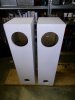
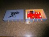
The crossover parts arrived today, and I got the two boards built. I installed one (after confirming they functioned as designed), and man it is a pain to solder in through the woofer hole - and to screw the board onto the back of the cabinet took some doing. I have set the screws into the second board, before I start soldering.

I dropped 3 screws down the back - so I had to tilt the cabinet forward so they would fall out of the terminus opening. Sheesh!

The next time I build a speaker, I will allow for a board that has the components on the inside, and the binding posts on the outside, and put T-nuts and screws from the back ...

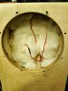
I modeled adding a fair bit of poly-fil in the 1st segment - 21oz in total with 2/3rds in the closed end, and the rest behind the woofer. But I only had an additional 10+ ounces, so I added 5+ oz to the 1oz already there, and left the 9oz behind the woofer.
 

Attachments

  • IMG_20210907_211602.jpg
    IMG_20210907_211602.jpg
    86.1 KB · Views: 40
  • IMG_20210907_211809.jpg
    IMG_20210907_211809.jpg
    114.2 KB · Views: 36
  • IMG_20210907_154453.jpg
    IMG_20210907_154453.jpg
    141.2 KB · Views: 36
Back
Top Bottom