• The move to the new server is done. There are some software and database maintenance updates in process. This has us passing the hat around to help out. We appreciate any donations. Seriously, even a dollar helps. The payment page may be found here - https://www.audiokarma.org/support.html

Mass Loaded Transmission Line Speakers

took me about 10 hrs last time I drove to Baltimore. best wishes.
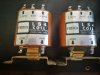
got a couple of those linaeaum mid/ tweets and mounted them on top of the yamaha ns 1000's. they definitely add a new dimension to the sound. came with 6.2k uf/250v caps (measure 6.4k uf / .6-.7 esr) and the bulb/fuse. suspect removing a few extra uf 's would tone it down. maybe a 4.5uf cap. interesting: they were connected in reverse polarity;with the cap on the negative terminal. the inductor is for a woofer. Plenty of bass,already. Yep; the 4.5uf cap was a significant positive change. Need to drop it further(too bright); maybe with a 2.7 uf cap and a 2.3mH inductor. Cool! Nice mid/tweets. Get'em while they're cheap. :banana:

I have noticed that the tweeters are wired in reverse on the Radio Shack speakers. I checked the polarity with a 9V battery and they are marked correctly - and I have them wired them in normal polarity. The fill in the crossover region is what it should be.
 
Interesting, as my ns 1000 tweets are wired in reverse. There's a reason for it; don't recall what it was. Possibly the same reason for the lineaums. A google should explain it. The lineaums do add a wide or dispersed dimension to the sound. Just need to tone them down; as they overwhelm and diminish the bass. Tried .3 mH inductor and 3.3uf caps- not there yet, but nice! :banana:lee morgan's the rajah and lee winchester's xylophone sounds better, already. will try the 2.7uf's. but, might end up also installing a pot- cymbals are too loud. might sound better with the allen organ 75's.
yes, 2.7uf or less and .3mH inductor in series.
 

Attachments

  • Screen Shot 2016-12-01 at 08.13.46.png
    Screen Shot 2016-12-01 at 08.13.46.png
    91.2 KB · Views: 21
  • IMG_20210915_200229402.jpg
    IMG_20210915_200229402.jpg
    35.9 KB · Views: 22
Last edited:
I have installed the revised crossover parts, and these speakers are now in their happy place! They sound better than the digital XO. I also added more poly-fil, so they now have ~21oz in total in the 1st and 2nd segments.

The way I would describe the sound is utterly open and clear and dynamic. Quiet music is exciting, with all the subtlety and detail and micro dynamics - pulling you into the music. Lyrics are right there with the singer's breath and diction easily audible. On well recorded acoustic songs, the lack of compression is startling.

The bypass capacitors also came today, but I am going to listen to them like this for a while. I think that because the tweeter cap is set at so low a frequency - it is basically not affecting the tweeter's natural roll off; and are just protecting the tweeter from get any bass. These Audyn Q4 caps are pretty darn good, so the bypass caps may be unnecessary?
 

Attachments

  • IMG_20210916_104946.jpg
    IMG_20210916_104946.jpg
    82.4 KB · Views: 35
  • IMG_20210916_114010.jpg
    IMG_20210916_114010.jpg
    107.3 KB · Views: 35
  • IMG_20210916_114652.jpg
    IMG_20210916_114652.jpg
    74.9 KB · Views: 34
That's a beautiful wood job on the top;lots of character. Reminiscent of when people cared about making things with artistic details. Nice! On the inductors,found that they don't usually measure what's advertised. Have had to remove a few windings to bring them to spec. :rockon:
 
That's a beautiful wood job on the top;lots of character. Reminiscent of when people cared about making things with artistic details. Nice! On the inductors,found that they don't usually measure what's advertised. Have had to remove a few windings to bring them to spec. :rockon:

How are you measuring the inductance?

The wood grain is just the luck of the draw, so to speak. I ordered two sheets of the Baltic birch, and they cut them for me.
 
How are you measuring the inductance?

The wood grain is just the luck of the draw, so to speak. I ordered two sheets of the Baltic birch, and they cut them for me.
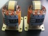
. One of those Chinese " test everything " testers. Found most inductors in speakers (and new ones) are not set per the schematic or their declared value. a larger valued inductor can be measured to desired length. Have made different values by unwinding them or adding wire. their soldering points have to be long enough to not change their setting. There's a formula involving several factors, including wire length, to create a set numbered inductor in Millihenry mH.
Is it worth the trouble and can you hear the difference.....:rflmao:
 

Attachments

  • inductor.jpg
    inductor.jpg
    77.3 KB · Views: 18
  • s-l1600.jpg
    s-l1600.jpg
    91.3 KB · Views: 17
Last edited:
I have been listening to the MLTL-10 speakers with the revised crossovers - and I could not be happier with their sound. Basically, the speakers have no sound of their own - each and every recording I play, sounds its best! The flaws in some recordings are revealed, and the life and spirit of many recordings, is just as evident.

The amp that gets them singing like this, is the B&K ST-140. I have recently replaced all the capacitors in the amp, and it makes this purity of sound just happen. My other amp, the Schiit Vidar is competent enough, but it sounds small and a bit two dimensional, and doesn't let the system "come to life" like the ST-140 does.

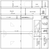
Someone on the DIY Audio forum made a very good suggestion - to redesign the bottom on the cabinet, to locate the terminus opening on the back. Their reason for this being better, was that any higher frequencies that exit that way would be less audible. And they're right - the Hornresp model shows more of this, than it is in reality, because the model is straight, and the speaker is "folded". Also, I have added eggcrate foam in the speaker, and Hornresp is not able to model foam.

But there is another reason to have the opening at the back - it is 18" / 45.7cm closer to the back wall, and the lowest frequencies that are coming mainly from the opening - below ~30Hz - will have greater room lift. Which makes this speaker truly full spectrum.
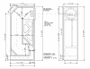
Here's the revised drawing - see attached image.

The F3 point predicted in Hornresp is awesomely low at 26.4Hz; and this is with less poly-fil than in the current version. I am also attaching the Hornresp screen capture.

The ripples at ~200Hz and up will largely be eliminated by the folded transmission line, and by eggcrate foam that I will installed in the bottom of the 3rd segment. The slight slope down below ~180Hz will probably help limit the room modes that I have in my room, and are usually present in most rooms. These speakers have more bass - and much better quality bass - than any speaker I have ever heard. And having significant bass all the way to 20Hz ( and slightly below!) in room - is so wonderful, I cannot find the words ...

A couple of other points that this revision improves on: the bottom of the closed end is angled at 45 degrees - the average distance (at the centerline) is the same as before, so the tuning of the chamber is fundamentally the same. BUT, it will have less standing waves, and will have a broader range of resonant frequencies.

In addition to the angle at the top back, I added an angle at the bottom - this is not for "turning" the air around the corner (this happens virtually the same without the angle, in this section very the air is moving back and forth) - but to break up standing waves.

 

Attachments

  • MLTL-10 Rev 2 Cabinet - Feet-Inch.png
    MLTL-10 Rev 2 Cabinet - Feet-Inch.png
    252 KB · Views: 54
  • MLTL-10 Rev 2 Response.png
    MLTL-10 Rev 2 Response.png
    131.4 KB · Views: 43
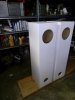
After building these 4 foot tall MLTL cabinets I blew out some dust left inside with a leaf blower. I was surprised that the sound that came out of the port was like a fog horn. Even with a single 8 inch driver they play so forcefully low a sub is really a waste.

P1010029.jpeg
 
On mid/tweet, using here a .3 mH inductor with a 2.7uf cap and the cymbals are still overwhelming on some songs, but kicking butt in others. just added a 2.6 ohm resistor as a pot substitute. No success. Next 1uf cap. thanks for sharing the design details. seen the post, thus edited q. thanks.
 
Last edited:
On mid/tweet,using here a .3 mH inductor with a 2.7uf cap and the cymbals are still overwhelming on some songs, but kicking butt in others. just added a 2.6 ohm resistor as a pot substitute. No success. Next 1uf cap. thanks for sharing the design details.

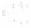
Ray, I am using the tweeter as low in frequency as it will go - and I am using a 1st order filter, and an L-pad on the tweeter. The first version of the crossover had a 33uF cap, and the current version has a 100uF. The first resulted in the XO frequency being around 2kHz, and the change dropped it to about 1.7kHz. That actually happened with about a 47uF or 56uF, if I remember correctly, but going all the way up to the 100uF let the response be a *touch* lower down. The tweeter rolls off on its own, and the big cap just protects it from "seeing" bass.

The L-pad is relative to the woofer I am using - it is two 6 ohm 12 watt resistors in parallel after the cap, and then a single 10 ohm 12 watt resistor to ground. This gets the tweeter level that sounds good, and the impedance is very even at about 7.5 ohms across the tweeter's bandwidth. See post #75 for the schematic of the first version of the crossover, and the edit mentioning the changes.
 
Okay, the ns 1000 tweets, mid, and mp3 recordings were causing the excessive cymbals. Lineaums add a wider dispersion of sound. Reminiscent of old school JVC & Panasonic boom-box tweets. Returning l pads to normal, overshadows them. Will tune them towards a tweeter.
using a 7kuf cap and 2.6 ohm resistors, moved to rear corners...much better.
 
Last edited:
The next pair of the MLTL-10 speakers that I build will be revised, to have the terminus opening at the lower back right at the floor. This will get a bit more room gain at the lowest frequencies.

I also will be cutting "punched" triangle holes through the side panels. This will add functional hand holds for when you are carrying the speaker. They are visibly showing the internal layout, which I think is important. I like to have the design drive the aesthetics. Form follows function!

And lastly- the triangles are effectively arrowheads that point toward the terminus opening at the bottom of the back of the speaker. Since you can't see it on the front, this just pleases my sense of the design.
 

Attachments

  • MLTL-10 Rev 3 Cabinet.png
    MLTL-10 Rev 3 Cabinet.png
    199.2 KB · Views: 62
  • MLTL-10 Rev 3 Panels.png
    MLTL-10 Rev 3 Panels.png
    303.3 KB · Views: 59
. One of those Chinese " test everything " testers.

Careful, some of those are OK, some are wildly inaccurate. I was having and issue with a power supply, could not get it right, took it to work where there are electrical engineers with expensive measuring equipment and my Chinese meter was way off causing me to think something was wrong when it wasn't. I've had the same issue with Chinese walwart power supplies not putting out what they advertise. Lots of junk out there.
 
I just found out the Dayton Audio DATS v3 measures both coils and capacitors, so checking these is easy as can be.

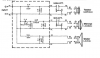
Here's the crossover schematic.
MLTL-10 Crossover.png
I didn't use the C3 bypass cap, because the Audyn A4 caps I used are plenty good enough.
 
I have built the analog crossovers for the MTLTL-11 speakers (with the 6" high TLS Linaeum tweeter) and today I removed the drivers, so that I could finish sanding the cabinets, at the same time. This way I only have to remove the drivers once, and get everything done. I had gotten to a certain point with the sanding, and I had to listen to them! They sound great, and today I finished the sanding. :-)

I pulled the steel wire lugs the binding posts came with (everything else is brass), and I bought copper ring connectors. The thought of the large crossover coils sitting within inches of the steel, didn't make me happy. All the wires can be soldered to the crossovers outside the cabinet, and the ring connectors can easily be fastened to the binding posts with a nut driver.

I am buying a right angle impact driver, that is much shorter front to back, so I can more easily screw the crossover boards to the back of the cabinet (with stainless screws). I will be adding a mesh panel to hold the polyfil up where it is supposed to be - some of it had fallen down into the back of the TL.

Then, I order another pair of woofers, and call the plywood supplier to have them cut two sheets of Baltic birch! These will be the revised version with the terminus opening at the bottom of the back - the F3 should be about 25Hz (vs 27Hz), so that's even better!
 
Nice work!

What is the total volume of the enclosure for the system that you show the simulation?

28Hz is a good choice for the l/4 tuning frequency.

Pete, I don't think I answered your question - the speakers I had at the Frankenfest are 77.85 liters, according to Hornresp.

The next pair I am going to build will have 79.966 liters.
 
Neil
Will a couple of percent difference in volume actually have a discernible effect? My impression was that there was a fair amount of slop in all measurements, and that, given manufacturing variances and changes in temperature, humidity and all that stuff, that slop was not of much concern. But maybe I am wrong.
 
Neil
Will a couple of percent difference in volume actually have a discernible effect? My impression was that there was a fair amount of slop in all measurements, and that, given manufacturing variances and changes in temperature, humidity and all that stuff, that slop was not of much concern. But maybe I am wrong.

Along with the volume change, the shape and lengths of section, and taper are different, too. I have found that Hornresp is quite accurate in predicting response.

You're right that there are many other factors, that we can't control, but reworking the cabinet will have benefits. Another boost is having the terminus in the back, means the room lift should be greater; so the combination of 2Hz greater extension and more room lift could let it hit below 20Hz.
 
IMG_20211119_140547.jpg I finished the first pair of speakers that I built, today - I built and installed the analog crossovers, and finished sanding them. In that process, I found that a piece of polyfil had fallen down into the end near the terminus opening. Which means that the bass was being damped, and so I installed some screws in the sides, to tie some yarn to, along with the wires, support it better, and keep it in place hopefully.

This correction (relocating the polyfil to where it should be), also brings up the bass a bit, so I may need to adjust the L-pad - I will listen for a few days, or a week, and see what I think after hearing a wide variety of music.

I'll take some photos of the cleaned up MLTL-11 cabinets, tomorrow. They have several flaws - chips in a few places, and where I had things not aligned as well, the first layer of the Baltic birch got sanded through. I switched from using small tenon in a dado slot (which is what caused the chipping), I used biscuits on the MLTL-10. This is much easier, and aligning things was *much* easier and more consistent.

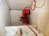
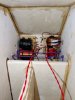
I used copper ring connectors to connect the wires to the binding posts - this was MUCH easier, because all the solder was done outside the cabinet. And it removed the steel tabs from the situation - as you can see, they would have been right next to the coils ...
 
Very interesting. although a bit on the large side, I guess really not much more than a comparable vented box of the same low frequency extension.
 
Back
Top Bottom