• The move to the new server is done. There are some software and database maintenance updates in process. This has us passing the hat around to help out. We appreciate any donations. Seriously, even a dollar helps. The payment page may be found here - https://www.audiokarma.org/support.html

MC7300 One Channel On Fritz

THere's a reason someone replaced that lamp regulator. I'm betting lifting the panel is still shorting out the lamp circuit and somehow getting 13VAC into the DC supply, or dropping the supply voltage. Try disconnecting that lamp board entirely and try lifting the panel.
 
Are you sure that the screws for the feet are the correct (stock) length? If they are too long, they can make contact with a PCB and create a short - possibly while lifting the unit.

Larry
 
Disconnected the meter board entirely, tried lifting the chassis. No buzzing (but with meters & PG unplugged, no way of knowing anything else). Noted that the left heat sink is still getting about 20degF hotter than the right heat sink.

Plugged in J1 (power supply from capacitor PCB). Lifted. Nothing.
Plugged in J4 (15VAC input). Lifted. Nothing.
Plugged in J2 & J3 (meters). Lifted. Nothing.
Plugged in J5 (PG). Right PG light on for some reason. Lifted. ZAP! Heard a short somewhere, on the L driver board saw R32 and R40 blow before I could unplug the unit.

Main fuse is good.

Have only lifted and checked R32 & R40 which are definitely blown. R32 is in the signal path in the +Drive circuit, R40 is in the +Limit circuit.

I hate hearing the "zap". Going to have to re-check everything now ... and try to figure out if it was connected to the meter board or not.

*Edit ... coming to the horrifying realization that if J6 - while unplugged - was resting on the pins just right to make connection, but one pin off, the right PG light would have seen the 12V power supply and illuminated ... maybe somehow causing a 12V PS short in the L channel signal path? I should have stopped dead in my tracks when I saw the R PG light on ... sigh
 
Last edited:
Ah crap, sorry about that.... looks like you now have some work to do on the driver and possibly the output transistors. Note that if you had P6 unplugged, nothing would be getting thru the driver board as the +/- 12V for the opamps etc comes from there.
 
Looks like output Q20 (an MJ15024) shorted and took out all 5 emitter resistors on the L channel positive heat sink, as well as R52L.

The rest of the pre-driver / driver / output devices and all other emitter resistors on the other three heat sinks are OK (well, I didn't pull the R channel heat sinks but the 4 resistors I could measure from the top are fine). On the R channel driver board, R32 and R40 are OK.

Did a pass through all transistors and diodes with my multimeter looking for shorts and didn't find any others.

So, total carnage as far as I can tell: Q20, R52L, R53 - R61, R32, R40.

I wonder if I should order the replacement MJ15024 from Mouser (in stock https://www.mouser.com/ProductDetail/onsemi/MJ15024G?qs=HVbQlW5zcXUxjTWGtPRWzg==), or directly from McIntosh.

Next I will power up on the DBT without heatsink boards connected, just to make sure my PS is OK.
 
Last edited:
I used the MJs on both my 2205 and 2500, each had one channel dead from shorted outputs. No discernable difference in distortion or response on the HP8903, compared to the stock outputs in the undamaged channels on each amp.
 
Thanks, good to know. The only other thing I need is that temperature switch I dislodged before ... which I can't find at all in the service manual / schematic. Maybe it's right in front of my nose but I can't find it. Will keep looking.

Powered it up on the DBT (I have a 53W bulb) with none of the plugs in the Capacitor board, and it came out of protection, bulb dimmed; then, I read 64V across C27 and C28. At least that seems OK. Now I guess I just gotta order these parts.
 
In the meantime ... not that I needed to, but I re-capped the electrolytics with a bunch of Nichicon UFG caps I had lying around anyway. Missing a couple that I didn't have in stock that I'll add to my Mouser order.

Went looking for past threads about this kind of thing ... found two, seems like they both were resolved by just making sure the wire harnesses were plugged in? I'm linking to MC300 threads since it seems to be, for all intents & purposes here, identical to the MC7300 ...

One: @jlovda took a bit of a detour with a driver board with his: thread. He wound up rebuilding one driver board so not sure what the ultimate fix was. Great success story though, what a great deal on an MC300!

Two: @william13 ended up having @Ray Gianelli check his out: thread. This seems to have been a loose driver board harness connection.

So it could have been that, although plugged in, maybe one or more of the wires in my meter board plugs wasn't making good contact. I'll see if I can investigate this with a multimeter while my parts are on their way from Mouser.
 
Last edited:
In the meantime ... not that I needed to, but I re-capped the electrolytics with a bunch of Nichicon UFG caps I had lying around anyway. Missing a couple that I didn't have in stock that I'll add to my Mouser order.

Went looking for past threads about this kind of thing ... found two, seems like they both were resolved by just making sure the wire harnesses were plugged in? I'm linking to MC300 threads since it seems to be, for all intents & purposes here, identical to the MC7300 ...

One: @jlovda took a bit of a detour with a driver board with his: thread. He wound up rebuilding one driver board so not sure what the ultimate fix was. Great success story though, what a great deal on an MC300!

Two: @william13 ended up having @Ray Gianelli check his out: thread. This seems to have been a loose driver board harness connection.

So it could have been that, although plugged in, maybe one or more of the wires in my meter board plugs wasn't making good contact. I'll see if I can investigate this with a multimeter while my parts are on their way from Mouser.
Actually it was the connectors that Mac uses. I had to take a small screwdriver and push the wires back in where the connector is supposed to "grab" them, for lack of a better word:
upload_2022-11-26_20-54-36.png
 
Thanks ... wow, upon closer inspection. These plugs are horrible. I remember trying to use "vampire" connectors in car audio many years ago and being eternally frustrated by intermittent connections.

Well, these look like they operate on the same concept. The pin inside the plug is terminated in a V-shaped slot on the top. The wire is pressed into this V-shaped slot which presumably cuts through the insulation and makes contact with the wire. One doesn't have to think too hard to imagine the possible bad connections that could result from improper pressing of the wire into the slot.

Took a pic of J8 which has two empty slots, so you can see the empty V-slots at the end of the pins.

PXL_20221127_024051520.jpg

NOW I see what you mean @Ray Gianelli , about pressing the wires into the plugs. It's not about seating the plugs on the pins, it's about seating the wires in the plugs.

Luckily it seems like easy to test with a multimeter with the plug disconnected.
 
I had the same trouble with this type of connector in a C34V I owned at one time. It was an intermittent ground connection on one of these white connectors on the monitor amp. Sent it to Terry DeWick but the problem did not appear. Found the problem by accident months later. I am very careful now to only pull these out by grabbing the sides. If they are really tight I use a tiny screwdriver to pry one side slightly up and then twisting the screwdriver head to raise the connector up. The problem was that the little knife blade did not puncture the wire insulation perfectly through the center of the wire. The blade ends up landing between the edge of the copper and the inside of the insulation. To fix it properly you must remove the wire, straighten the blade and then rotate the wire to puncture a new location. There are two little pieces of metal that go over the top of the wire to lock it down. These must be bent back to the correct position. A tiny flat bladed screwdriver was my tool.
 
Last edited:
New parts are installed, it's back together. For fun here are some pics:

New output & new emitter resistors on the L channel (-) heat sink.

PXL_20221203_235415858.jpg

PXL_20221203_235404326.jpg

The (mostly) recapped boards.

PXL_20221203_221511805.jpg

It seems mostly the same as it was. I'm getting +/- Drive and Bias voltages that match the reference voltages roughly the same as before, although I didn't write them down, and 0.00X V at the outputs.

On, with nothing plugged into the back:
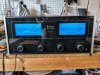
PXL_20221204_204529441.jpg

Putting the 1kHz sin wave back in it, with no load connected to the speaker terminals ... it's exhibiting the same symptom as before - the right channel is fine, the meter reading somewhere around the middle, but the left meter goes up much more quickly and into protection along with a buzzing sound.

If I unplug J4, the 15VAC input, no more buzzing. Of course, without J4 connected, I get no meters or protection lights, so all I know is that it doesn't buzz any more.

As before, after the buzzing session, the left heat sinks were immediately 20degF hotter than the right (~88deg vs. ~68deg after a very short time being on). Getting REALLY hot is C16 in the left driver board. In under a minute, it was reading 100+degF! It will get this hot even with no input signal at all.

I'm waiting for them to cool back down. Once cooled, I will try it again with J4 unplugged and see if the heat sink & C16(L) temps continue to differ (which is, without the meters, an easy way of seeing if there's still something funny with the left channel even if it's no longer buzzing).

I figure if they are even temps with J4 unplugged, that confirms the issue is in the meter/regulator PCB - as we originally suspected, but I want to make sure I fixed all the collateral damage from the J6 *uck-up. :oops:
 
Last edited:
Turns out that C16L heats up fast even with no input signal at all and with J4 unplugged. I turned the unit off when the capacitor hit 100degF.

Now, need to figure out why ... maybe I missed something that blew in the Left driver board before. I may start by swapping driver boards and see if it heats up on the other side.
 
Swapped driver boards L / R and the hot C16 stays on the left channel. Shoot - so I guess I need to look upstream (87V power supply) or downstream (Q3A?) ...
 
If that cap is heating up, it's shot. Might have gotten it in reverse polarity. Triple check vs the schematic when you replace it. THat's strange since there should be pretty much zero volts there. Might bear checking the voltage around Q13.

I'm wondering if the thing is oscillating ultrasonically, which might explain much of this including the cap heating up. Look at the output with a scope, or AC voltmeter with no signal, but advance the volume control.

Disconnecting the 15VAC in will also kill the +/-12V and -6V supplies, which the preamp depends upon. Not sure how you're getting audio thru it with those supplies killed.

Instead try disconnecting J5, which goes to the PG board and see what happens.
 
C16 is in there correctly and is a brand new cap ... no solder bridges, looks 100% fine and correct. So I'm stumped. I may pull it out and test it to make sure.

In the meantime, the right meter has started picking up something and won't rest at idle with nothing connected. It stays a little bit up and twitches a little. The left meter is nice and dead at idle. With the 1kHz test tone, the right channel does not go into protection while the left channel still acts like it has much more bias and goes into protection with the buzzing sound coming from the chassis. That said, maybe I'm imagining it, but both meters seemed to twitch a bit regardless of amplitude with the test tone. It was weird.

I disconnected J5 but no change.

Then I disconnected J3, J4, and J5 on each driver board, and at idle the right meter continues to be a little bit raised, and twitching (or maybe my imagination).

So in sum - still no progress with the left channel protection / bias / buzz issue. But have isolated the right channel meter issue to something upstream of the heatsink PCBs ... so that's something.
 
Back
Top Bottom