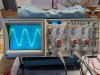
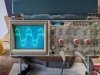
I can't fathom a reason why the scope itself would be an issue if you have the probes set to 10X. The probe tip should have a 10 megohm resistor in series with the input and should be adequate to provide a low-capacitance point suitable for probing RF circuits, let alone audio. When it does this, do you also have the Ch1 probe hooked up?
I'm thinking you have a ground loop problem of some sort. THe scope undoubtedly has a three-wire plug - not sure if the 7300 does also. You really only need one ground wire from the probe, try it with just the Ch1 ground probe connected. Might be some kind of capacitive coupling groing on with the wires you have on your dummy loads between your input device/wiring, scope/wiring, etc causing an oscillation - but then there wasn't an oscillation apparent on your screenshot when that was happening, was there?
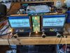
All that said, this could be pointing towards an issue with the amp. The amp *should* be able to drive almost any sort of load at low levels without groaning and heating up like it is, even if the scope is somehow screwed up. I further note that the meters' power reading seems to be quite a bit higher than what we're seeing at the output. That could be because the meters are not correctly adjusted - OR it could be indicative of a phasing issue with the autoformers, feedback network, or something else. Note that the 7300 has a metering circuit that actually measures power - it has a current transformer which sends a voltage to the meter amp correlating to audio current draw through the autoformer, AND a audio voltage measurement point. You've had those boards disconnected as I recall - are the plugs that go to the autoformers in correctly?
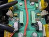
Finally I note all kinds of intermittent issues you've had. I note a subtle but potentially important difference between the right and left channel autoformer wiring: the left channel COM lead is grounded to the chassis whereas the right channel autoformer is NOT grounded to the chassis. The only other chassis ground point is the input connectors and the bypass capacitor on the AC input. Note differences between right and left on the capacitor board - red and green circled points.
I further note discrepancies between the schematic, the chassis wiring diagram, and the capacitor board PCB layout with respect to the numbering of the four SP3 leads, going to the autoformer. There's obviously some stuff going on on the capacitor PCB that's not exactly clear on its diagram - probably flying leads. Somehow the COM lead from the right autoformer's gotta get to the ground point, and that's not shown on the PCB diagram, but it is shown on the schematic.
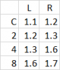
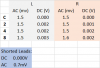
Now... what to do with this? I'd take a resistance reading between each autoformer COM to the chassis. Should be a dead short. Then go up each tap and read resistance to ground - should be very low but increasing as you go up the taps. Is there a discrepancy between the two channels?
The other thing I'd do is double check that each J3 on the capacitor PCB is oriented correctly, and not intermittent. THe respective J3s provide the chassis ground to the driver, as well as feedback to the driver. Note that in the capacitor PCB diagram (below, green circle), J3-1R doesn't have a connection to that pin - but it should I would expect have a flying lead to it - OR they're relying upon J3R for the ground. Anyhow, I hope this isn't a red herring but the behavior of the amp when connected a certian way with the scope is indication that something's not right with the amp, and a grounding issue associated with the output (thru the scope and/or power line) might be the problem here.