

You are using an out of date browser. It may not display this or other websites correctly.
You should upgrade or use an alternative browser.
You should upgrade or use an alternative browser.
MC7300 One Channel On Fritz
- Thread starter Johnny_Law
- Start date
-
- Tags
- distortion mc7300 protection

Yes, I have an old Tek scope - but I'm a bit of a novice with it. I suppose I'll start by hooking the heat sinks back up and hooking up my 8ohm dummy loads, attaching probes to those.
In the meantime I turned the unit on again this morning, in the same state (no input connected, heat sink PCBs disconnected from driver boards), and now the R meter is behaving normally again. I tried to gently massage the meter PCB's connectors with a wooden stick, but nothing caused it to move back to how it was acting yesterday.
So - another intermittent problem. Dang!
In the meantime I turned the unit on again this morning, in the same state (no input connected, heat sink PCBs disconnected from driver boards), and now the R meter is behaving normally again. I tried to gently massage the meter PCB's connectors with a wooden stick, but nothing caused it to move back to how it was acting yesterday.
So - another intermittent problem. Dang!

You might want to rig up a dim bulb tester (it's descirbed here on AK somewhere) so it limits input current if the amp goes wonky again.
A scope would be invaulable here. What model scope is it, I can give you hints on how to set it up to troubleshoot this. Do you have a 10X probe?
A scope would be invaulable here. What model scope is it, I can give you hints on how to set it up to troubleshoot this. Do you have a 10X probe?
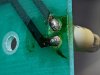
I think I solved the blinking MC7300 light - which appears to have been caused by a bad solder joint. So, good news, but offers no further clues into the main issue which is a bit disappointing.
Before:
After:
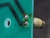
I do have a DBT and used it when rebuilding with the new components, but seeing no voltage in the signal path I went back into the wall. The 43W bulb I'm using stays pretty bright at idle.
The scope I have is a Tek model 2235 or 2236. I do have 10x probes.
Before:
After:
I do have a DBT and used it when rebuilding with the new components, but seeing no voltage in the signal path I went back into the wall. The 43W bulb I'm using stays pretty bright at idle.
The scope I have is a Tek model 2235 or 2236. I do have 10x probes.
Use a 100W bulb, you're getting too much voltage drop across the 43W bulb. Also needs to be incandescent, not a LED lamp.
Set the scope to .1V/div (which would be 1V with the 10X probe), 10 mS or 50 ms sweep. First, disconnect any signal sources and set the input gain of the amp to about halfway. Go thru the bad stage with your probe, starting at the input and go foward thru the driver and end at the speaker terminals, see if there's a large(ish) signal which would be indicative of an oscillation. If all OK, then feed it a sine wave signal and trace it from the input forward thru the driver. You should be able to see where it starts distorting, if it is. You can probe thru each stage at the same point and see where you're losing gain on the left channel. You could use the dual trace capability of your scope by setting both channels on the scope the same, trigger on the right channel, feed a sine wave to both channels via a Y adapter or use a clip lead to strap the inputs together, then put your probes in the same place in each channel of the amp as you go thru it. If that scope has "A-B" capability you can actually have the scope display the difference between the two signals.
Set the scope to .1V/div (which would be 1V with the 10X probe), 10 mS or 50 ms sweep. First, disconnect any signal sources and set the input gain of the amp to about halfway. Go thru the bad stage with your probe, starting at the input and go foward thru the driver and end at the speaker terminals, see if there's a large(ish) signal which would be indicative of an oscillation. If all OK, then feed it a sine wave signal and trace it from the input forward thru the driver. You should be able to see where it starts distorting, if it is. You can probe thru each stage at the same point and see where you're losing gain on the left channel. You could use the dual trace capability of your scope by setting both channels on the scope the same, trigger on the right channel, feed a sine wave to both channels via a Y adapter or use a clip lead to strap the inputs together, then put your probes in the same place in each channel of the amp as you go thru it. If that scope has "A-B" capability you can actually have the scope display the difference between the two signals.
On a whim I swapped the driver boards back around and for kicks turned it on with no input in.
Both meters looked fine. Huh.
Put in a 1kHz test tone, raised gain, both meters fine and even. Huh.
Hooked up my speakers, played music, has sounded killer for a few hours now. Like before, the L channel heat sinks are at ~110degF, R channel heat sinks are at ~90degF, but both stable.
Brian Bromberg, Bruce Cockburn, Tool, Metallica, Nils Lofgren, meters showing 3W max (this is my phone's max output via headphone out, 8ohm taps into JBL 030 loads in C40 cabs), all good, sounds awesome.
Huh.

I'm heading home for the next three weeks, so I'll pick it back up in Jan, get my dummy loads and scope out. But it sure seems like it might be intermittent-harness-connection-related.
Both meters looked fine. Huh.
Put in a 1kHz test tone, raised gain, both meters fine and even. Huh.
Hooked up my speakers, played music, has sounded killer for a few hours now. Like before, the L channel heat sinks are at ~110degF, R channel heat sinks are at ~90degF, but both stable.
Brian Bromberg, Bruce Cockburn, Tool, Metallica, Nils Lofgren, meters showing 3W max (this is my phone's max output via headphone out, 8ohm taps into JBL 030 loads in C40 cabs), all good, sounds awesome.
Huh.
I'm heading home for the next three weeks, so I'll pick it back up in Jan, get my dummy loads and scope out. But it sure seems like it might be intermittent-harness-connection-related.
Last edited:
OK I'm back. Got the scope hooked up. Ran a 1kHz test tone through it.
First, I should note my uneven meter is back. I've narrowed this down to the Meter PCB - but I'll have to come back round to this. I wanted to run the test tone through the scope and see what happened.
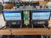
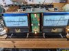
Here's what the meters look like with the unit on, gain at 0 for both channels, no input pugged in. Note the right meter.
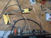
Here's my 8ohm dummy loads connected to the 8ohm taps, and my 10X probes connected across the dummy loads.
I'm using an RCA to 3.5mm microphone cable into my Pixel 5a with an app called "Hz" that generates test tones. I put in a 1kHz tone with the Pixel's volume all the way up, and then turned the gain all the way up on both channels.
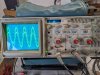
Here's the scope. Signals look clean.

With the signals on top of each other (one of them had a phantom amplitude gain thanks to an old probe that went away when I wiggled it ... anyone have a good source for new probes?) - looks like each channel is clean and even.
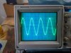
So ... I think that confirms both channel is working fine, at least now, at rest on the bench. Let me know if anything looks off in terms of methodology / observation / etc. This is only my second time ever using my scope (which I bought used).
First, I should note my uneven meter is back. I've narrowed this down to the Meter PCB - but I'll have to come back round to this. I wanted to run the test tone through the scope and see what happened.
Here's what the meters look like with the unit on, gain at 0 for both channels, no input pugged in. Note the right meter.
Here's my 8ohm dummy loads connected to the 8ohm taps, and my 10X probes connected across the dummy loads.
I'm using an RCA to 3.5mm microphone cable into my Pixel 5a with an app called "Hz" that generates test tones. I put in a 1kHz tone with the Pixel's volume all the way up, and then turned the gain all the way up on both channels.
Here's the scope. Signals look clean.
With the signals on top of each other (one of them had a phantom amplitude gain thanks to an old probe that went away when I wiggled it ... anyone have a good source for new probes?) - looks like each channel is clean and even.
So ... I think that confirms both channel is working fine, at least now, at rest on the bench. Let me know if anything looks off in terms of methodology / observation / etc. This is only my second time ever using my scope (which I bought used).
Now, about the uneven meter. This has me stumped.
I worked from the meters backwards to try to isolate the issue.
-Unplugging the meter completely (J3), the needle stays at rest at 0. So, confirmed it's not a physical meter needle issue.
-Swapping the meter harnesses (J2 to J3), the issue moves to the left meter. So, confirmed it's present at J3 at the Meter / Regulator PCB.
-Unplugged the Driver board, the issue remains. So, confirmed it's not coming from the Driver board.
-Unplugged the Heat Sink boards, the issue remains. So, confirmed it's not coming from the outputs.
This means - from my reasoning above - the issue is coming from within the Meter / Regulator PCB.
So, I measured DC voltage across pins 3 and 4 of J2 (0.01V) and J3 (0.05V). This tells me that perhaps the issue is from an extra 0.04V at pin 4 of J3. (I measured AC voltage as well, no difference.)
Also note that the meter seems to respond to amp output the same as the other meter, with the exception of being a little higher all the time, as proven by the test with the scope. It's as if everything is fine, but somewhere along the line it's getting a little bit of extra DC voltage. The question is where.
Taking the Meter / Regulator Board out, I measured (in circuit) each resistor (ohms), diode, and transistor (both using the diode tester of my DMM), and couldn't find anything clearly amiss or uneven between the channels.
... So that's where I'm at. Pretty sure it's an issue within the Meter / Regulator Board, and extra DC voltage at J3 Pin 4 seems to be a plausible cause of the excited meter, but I have not been able to identify the culprit.
I can't figure out how to measure any values with the board in circuit since it slides tightly between the transformer and the face plate, so I think my next step is to take the face plate bracket off so I can access the board and take measurements with the power on.
I worked from the meters backwards to try to isolate the issue.
-Unplugging the meter completely (J3), the needle stays at rest at 0. So, confirmed it's not a physical meter needle issue.
-Swapping the meter harnesses (J2 to J3), the issue moves to the left meter. So, confirmed it's present at J3 at the Meter / Regulator PCB.
-Unplugged the Driver board, the issue remains. So, confirmed it's not coming from the Driver board.
-Unplugged the Heat Sink boards, the issue remains. So, confirmed it's not coming from the outputs.
This means - from my reasoning above - the issue is coming from within the Meter / Regulator PCB.
So, I measured DC voltage across pins 3 and 4 of J2 (0.01V) and J3 (0.05V). This tells me that perhaps the issue is from an extra 0.04V at pin 4 of J3. (I measured AC voltage as well, no difference.)
Also note that the meter seems to respond to amp output the same as the other meter, with the exception of being a little higher all the time, as proven by the test with the scope. It's as if everything is fine, but somewhere along the line it's getting a little bit of extra DC voltage. The question is where.
Taking the Meter / Regulator Board out, I measured (in circuit) each resistor (ohms), diode, and transistor (both using the diode tester of my DMM), and couldn't find anything clearly amiss or uneven between the channels.
... So that's where I'm at. Pretty sure it's an issue within the Meter / Regulator Board, and extra DC voltage at J3 Pin 4 seems to be a plausible cause of the excited meter, but I have not been able to identify the culprit.
I can't figure out how to measure any values with the board in circuit since it slides tightly between the transformer and the face plate, so I think my next step is to take the face plate bracket off so I can access the board and take measurements with the power on.
Last edited:
Well ... let's call it an intermittent meter issue. Because it disappeared (again). Turned it on to continue diagnosis and poof, even meters! 
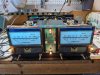
I then realized that I have never calibrated my scope. So I have no idea if the signals are REALLY exactly even or whether my calibration is just off. Easy to mess with the calibration to make them identical ...

And then with the 1kHz signal turned off, with both sides at max gain still, the scope at least showed identical DC signals.

Thinking practically, with the uneven meter issue, since it's intermittent, I believe it's not a resistor, but maybe a diode or transistor? Which both can fail intermittently before fully failing.
My other idea is to swap components channel to channel, one at a time, to see if anything specific causes the issue to switch sides.
I then realized that I have never calibrated my scope. So I have no idea if the signals are REALLY exactly even or whether my calibration is just off. Easy to mess with the calibration to make them identical ...
And then with the 1kHz signal turned off, with both sides at max gain still, the scope at least showed identical DC signals.
Thinking practically, with the uneven meter issue, since it's intermittent, I believe it's not a resistor, but maybe a diode or transistor? Which both can fail intermittently before fully failing.
My other idea is to swap components channel to channel, one at a time, to see if anything specific causes the issue to switch sides.
edit - typed the below while you were posting also.
Signal looks really good, and that you have exactly the same voltage on each channel is good also.
First comment, looks like your meters are reading a bit high. Meters should read RMS, you have 10V P-P, so that's ((10/2.828)^2)/8=1.56 W RMS and your meters are reading 20-30. That is assuming I'm seeing 2V/division on your scope.
Second, the meter is reading a bit up off zero because as you note J3/4 has a bit of voltage - that directly drives the meter - and should be ~0V at no signal.
There are a bunch of op amps in that circuit and a bit of DC offset on one will propagate throughout the circuit and result in a non-zero quiescent reading, as you're getting. Could also be a leaky transistor. Take voltage readings at Q13, Q11, and pin 7 (op amp output) of ICs 3, 4, and 5. Compare with schematic values, and we can go from there.
I'd also hit J1 pins 4 and 5 with your scope as sensitive as it'll go and see if you have a bit of noise or an ultrasonic oscillation going on thats causing the meter to go off zero.
Signal looks really good, and that you have exactly the same voltage on each channel is good also.
First comment, looks like your meters are reading a bit high. Meters should read RMS, you have 10V P-P, so that's ((10/2.828)^2)/8=1.56 W RMS and your meters are reading 20-30. That is assuming I'm seeing 2V/division on your scope.
Second, the meter is reading a bit up off zero because as you note J3/4 has a bit of voltage - that directly drives the meter - and should be ~0V at no signal.
There are a bunch of op amps in that circuit and a bit of DC offset on one will propagate throughout the circuit and result in a non-zero quiescent reading, as you're getting. Could also be a leaky transistor. Take voltage readings at Q13, Q11, and pin 7 (op amp output) of ICs 3, 4, and 5. Compare with schematic values, and we can go from there.
I'd also hit J1 pins 4 and 5 with your scope as sensitive as it'll go and see if you have a bit of noise or an ultrasonic oscillation going on thats causing the meter to go off zero.
Your scope should have a built in calibrator point, its the little hole marked "probe adjust" just above the focus knob. You should get a 1KHz square wave of 500 mV (1/2V) p-p. The square wave should be nive and square, if not, adjust the probe compensation screw on the probe. The red knobs should be twisted all the way clockwise so they click, thats the position that will allow you to read voltage from the screen.
Thanks. I do see a "probe adjustment" hole in the front face (and found section 2-15 "Probe Compensation" of the User Manual which refers to it).
Went ... OK for Channel 1. A little weird looking.
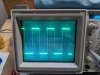
Channel 2, however ... for starters it looked like a garbled mess.
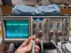
I played with the "Var Holdoff" knob in the upper-rightmost part of the scope's instrument panel and the lines slowed down but still moved left to right. I was able to calibrate the amplitude of the square wave correctly, but the square waves continued to move horizontally.
Here's what it looked like:
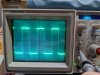
I swapped probes between channels, same result on Channel 2.
Three things:
(1) There appears to be a Channel 2 issue, not a probe issue.
(2) It concerns me that the square waves on Channel 2 were moving horizontally when they were perfectly stationary on Channel 1. I don't know what this means or how to fix it.
(3) From the User Manual, Fig. 2-11 Probe Compensation leads me to believe that the Channel 2 is Over Compensated.
Finally, how could this happen if Channel 2 was doing just fine measuring the 1kHz wave out of the MC7300?!
Went ... OK for Channel 1. A little weird looking.
Channel 2, however ... for starters it looked like a garbled mess.
I played with the "Var Holdoff" knob in the upper-rightmost part of the scope's instrument panel and the lines slowed down but still moved left to right. I was able to calibrate the amplitude of the square wave correctly, but the square waves continued to move horizontally.
Here's what it looked like:
I swapped probes between channels, same result on Channel 2.
Three things:
(1) There appears to be a Channel 2 issue, not a probe issue.
(2) It concerns me that the square waves on Channel 2 were moving horizontally when they were perfectly stationary on Channel 1. I don't know what this means or how to fix it.
(3) From the User Manual, Fig. 2-11 Probe Compensation leads me to believe that the Channel 2 is Over Compensated.
Finally, how could this happen if Channel 2 was doing just fine measuring the 1kHz wave out of the MC7300?!
Last edited:
You're just not triggering on Channel 2. Select Ch2 on the trig select just to the right of the time base knob.
To adjust the probe to a good square wave, there should be a screw adjust (probe compensation) at the base of the probe body where it connects to the scope., with the probe connected to the probe adjust terminal.
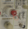
To adjust the probe to a good square wave, there should be a screw adjust (probe compensation) at the base of the probe body where it connects to the scope., with the probe connected to the probe adjust terminal.
Thanks. Still learning how to use this thing.
Channel 1 ...
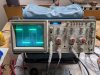
Channel 2 ...

Neither probe's adjustment screw at its base did anything at all. Maybe time to find new probes?

Channel 1 ...
Channel 2 ...
Neither probe's adjustment screw at its base did anything at all. Maybe time to find new probes?
The probe compensation will not adjust the level, just the shape of the square wave. Ch1 looks OK. Make sure you have the probe on X10. Try swapping probes between the two channels, could be Ch2 issue in the scope.
It looks like you have 5 divisions, and that probe adjust signal should be 500 mV (although it says ~500mV so it's not going to be exact), and your range switch is at either 50 mV/div or .5V/div, which would mean either 250 mV or 2.5V on your display, depending upon whether you have the probe at X1 or X10. Wonder if the switch or knob has slipped a range. However I note both channels respond identically so it's probably the probe adjust output that's incorrect. I wouldn't worry too awfully much about this, but you noted that one of the probes had an intermittent. You can easily get by with 25 MHz probes for audio, if you find some cheap.
One way to find out is to set the scope to DC, probe X1, 1V/div, set the trace to the center, then put your probe on a 5V source. The trace should move up 5 divisions. Do the same with the probe at X10 and the range at 0.1V/div. The trace should move up 5 divisions.
It looks like you have 5 divisions, and that probe adjust signal should be 500 mV (although it says ~500mV so it's not going to be exact), and your range switch is at either 50 mV/div or .5V/div, which would mean either 250 mV or 2.5V on your display, depending upon whether you have the probe at X1 or X10. Wonder if the switch or knob has slipped a range. However I note both channels respond identically so it's probably the probe adjust output that's incorrect. I wouldn't worry too awfully much about this, but you noted that one of the probes had an intermittent. You can easily get by with 25 MHz probes for audio, if you find some cheap.
One way to find out is to set the scope to DC, probe X1, 1V/div, set the trace to the center, then put your probe on a 5V source. The trace should move up 5 divisions. Do the same with the probe at X10 and the range at 0.1V/div. The trace should move up 5 divisions.
Thanks - I have no idea how I did that. I took a AA battery that measured 1.1V with my DMM and measured it with the probes, both read it correctly.
This evening I was able to - as well as I could - calibrate the probes correctly.
After initial calibration, I swapped them between channels and found they needed to be calibrated again. Each channel and each probe must have its own unique signature. Here's the same probe in Channel 1 and Channel 2 (noting that it's calibrated across 0.5V this time):
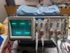

So then I connected the probes to the same setup (8ohm dummy loads in 8ohm taps) with the same 1kHz test tone out of my Pixel 5a via 3.5mm to RCA cord.
However, now I'm only seeing ~3W on the meters with max gain. Before they were showing ~30W. NO idea why it changed ... I didn't change a thing! I need a function generator ... I'm assuming there's some volume setting on my phone that changed. Or hoping, anyway, that it was a setting in my phone and not something malfunctioning in the MC7300 ... but I have no idea.

This is both channels on top of each other. At first glance, the channels are lying on top of each other pretty well.
The sin wave shows ~6.75 blocks peak to peak so call it 6.75V. V = IR so 6.75V = I * 8ohms. Solving for I, we get I = 6.75/8 = 0.84A. Amps = Watts / Volts, solving for Watts we get 0.84A * 6.75V = 5.7W. Hmph. That's not what the MC7300 is showing ... the meters are showing about half of that (unless I made a mistake somewhere, or unless my 8ohm dummy loads aren't actually 8ohms?)
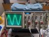
But that's not the worst part. I then added the channels to each other, the inverted Channel 2. Looks like the channels are uneven ... I am seeing a sin wave with about 0.4V peak to peak, the same frequency as the input signal.

So I've got meters that are way off and channels that are uneven. I'd like to figure out some other way to check each, so I can verify that each is actually true.
(And I keep waiting for the uneven meter issue to come back - the testing above was done with both meters at 0 at rest.)
This evening I was able to - as well as I could - calibrate the probes correctly.
After initial calibration, I swapped them between channels and found they needed to be calibrated again. Each channel and each probe must have its own unique signature. Here's the same probe in Channel 1 and Channel 2 (noting that it's calibrated across 0.5V this time):
So then I connected the probes to the same setup (8ohm dummy loads in 8ohm taps) with the same 1kHz test tone out of my Pixel 5a via 3.5mm to RCA cord.
However, now I'm only seeing ~3W on the meters with max gain. Before they were showing ~30W. NO idea why it changed ... I didn't change a thing! I need a function generator ... I'm assuming there's some volume setting on my phone that changed. Or hoping, anyway, that it was a setting in my phone and not something malfunctioning in the MC7300 ... but I have no idea.
This is both channels on top of each other. At first glance, the channels are lying on top of each other pretty well.
The sin wave shows ~6.75 blocks peak to peak so call it 6.75V. V = IR so 6.75V = I * 8ohms. Solving for I, we get I = 6.75/8 = 0.84A. Amps = Watts / Volts, solving for Watts we get 0.84A * 6.75V = 5.7W. Hmph. That's not what the MC7300 is showing ... the meters are showing about half of that (unless I made a mistake somewhere, or unless my 8ohm dummy loads aren't actually 8ohms?)
But that's not the worst part. I then added the channels to each other, the inverted Channel 2. Looks like the channels are uneven ... I am seeing a sin wave with about 0.4V peak to peak, the same frequency as the input signal.
So I've got meters that are way off and channels that are uneven. I'd like to figure out some other way to check each, so I can verify that each is actually true.
(And I keep waiting for the uneven meter issue to come back - the testing above was done with both meters at 0 at rest.)
First, I wouldn't worry much about the unevenness. Could be difference in the scope channel, imbalance in the scope's subraction, etc, but even if not, it's only a 0.6 dB difference in voltage. That both traces overlay pretty well indicates something this probably isn't a problem.
Second, first probe cal looks good but the second one is a bit wonky. Could be the probe or the scope channel. That could also be the reason for the imbalance discussed above.
Second, your meter issue is even worse than you think, since you did your calculations with peak rather than RMS voltage. Vrms=Vp-p/2.828 so your RMS voltage (which we'll need to calculate RMS power) is 6.75/2.828=2.38Vrms. P= (V^2)/R = (2.38^2)/8 = 5.69/8= 0.712 Wrms. So your meters are reading quite a bit optimistically. Is that dummy load resistor warming up at all?
You probably want to adjust them at a higher power level. I see you have your dummy load resistors sitting out in the open - you might want to screw them down to an old heatsink, or large piece of metal using some heatsink grease. I'd think calibration at 30W (about midscale) could give you decent accuracy. Not sure what the resistors are rated for but they do need to be heatsinked, give it a few seconds blast of audio (one channel at a time) which hopefully will give you enough time to adjust the meter. So, 30W(RMS) = V^2/8; sqrt(30*8)= sqrt(240)=15.5 VRMS; Vp-p=2.828*Vrms=2.828*15.5=43.84V P-P
However, before you do so, take a look at the output of the sig gen with the scope to see how much voltage it's putting out for a given meter reading. If the sensitivy switch is in the 1.5V position then 1.5Vrms input should drive the amp to full output. Remember your P-P vs RMS conversions!
Second, first probe cal looks good but the second one is a bit wonky. Could be the probe or the scope channel. That could also be the reason for the imbalance discussed above.
Second, your meter issue is even worse than you think, since you did your calculations with peak rather than RMS voltage. Vrms=Vp-p/2.828 so your RMS voltage (which we'll need to calculate RMS power) is 6.75/2.828=2.38Vrms. P= (V^2)/R = (2.38^2)/8 = 5.69/8= 0.712 Wrms. So your meters are reading quite a bit optimistically. Is that dummy load resistor warming up at all?
You probably want to adjust them at a higher power level. I see you have your dummy load resistors sitting out in the open - you might want to screw them down to an old heatsink, or large piece of metal using some heatsink grease. I'd think calibration at 30W (about midscale) could give you decent accuracy. Not sure what the resistors are rated for but they do need to be heatsinked, give it a few seconds blast of audio (one channel at a time) which hopefully will give you enough time to adjust the meter. So, 30W(RMS) = V^2/8; sqrt(30*8)= sqrt(240)=15.5 VRMS; Vp-p=2.828*Vrms=2.828*15.5=43.84V P-P
However, before you do so, take a look at the output of the sig gen with the scope to see how much voltage it's putting out for a given meter reading. If the sensitivy switch is in the 1.5V position then 1.5Vrms input should drive the amp to full output. Remember your P-P vs RMS conversions!
Measured my Pixel 5a's output, 1kHz test tone at max volume:
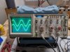
I count 3.5 divisions, at 0.1V/div, giving 0.35V peak to peak or (0.35V * 0.7071 =) 0.25V RMS.
With the MC7300's input impedance at 2.5V, this is an easy calculation: I should be seeing 10% of the rated 300W, or 30W, on the meters, like I was before ... (assuming the amp's gain is linear in relation to input impedance - I can't find any technical documentation to confirm this) ...
... However, as we saw before, the MC7300's meters are showing 3W, and the calculations above are saying 0.7W (although - looking back on our calculations just above ... 1V/div at 6.75V/div = 6.75Vpeak = 4.8VRMS; over 8 ohms that's 2.9W right? So maybe the meters ARE right after all ... but it should still be making 10x that power given the input signal noted here...)
EDIT: I am an idiot. I had turned the gain down on both channels. But because the knobs aren't on, I didn't see that the gain was low. WOOPS! So that explains why the power output was so much lower ... I will turn them up and see if I get 30W again. This is probably also why the channels were uneven before.
Stay tuned.
I count 3.5 divisions, at 0.1V/div, giving 0.35V peak to peak or (0.35V * 0.7071 =) 0.25V RMS.
With the MC7300's input impedance at 2.5V, this is an easy calculation: I should be seeing 10% of the rated 300W, or 30W, on the meters, like I was before ... (assuming the amp's gain is linear in relation to input impedance - I can't find any technical documentation to confirm this) ...
... However, as we saw before, the MC7300's meters are showing 3W, and the calculations above are saying 0.7W (although - looking back on our calculations just above ... 1V/div at 6.75V/div = 6.75Vpeak = 4.8VRMS; over 8 ohms that's 2.9W right? So maybe the meters ARE right after all ... but it should still be making 10x that power given the input signal noted here...)
EDIT: I am an idiot. I had turned the gain down on both channels. But because the knobs aren't on, I didn't see that the gain was low. WOOPS! So that explains why the power output was so much lower ... I will turn them up and see if I get 30W again. This is probably also why the channels were uneven before.
Stay tuned.
Last edited:
[Edit: Disregard the below! This is what happens when a probe /ground is hooked up backwards on one channel's dummy load!]
Hooked up the same 1kHz test tone via Pixel 5a.
Turned the gain all the way up. Right channel WAY higher than left.
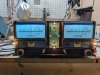
Noticed that the channels are affecting each other. With the L channel's gain all the way down, and the R channel's gain all the way up ...
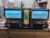
With the L channel's gain all the way up and the R channel's gain all the way down ...
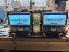
As a check, with both channels' gain all the way down:
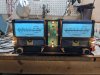
The right channel's heat sinks got HOT very fast. The left channel's heat sinks stayed ambient.
Both dummy loads stayed ambient.
And the scope didn't pick up enough of a signal out of the right channel to even trigger.
This is an entirely new situation... I am out of time tonight.
Hooked up the same 1kHz test tone via Pixel 5a.
Turned the gain all the way up. Right channel WAY higher than left.
Noticed that the channels are affecting each other. With the L channel's gain all the way down, and the R channel's gain all the way up ...
With the L channel's gain all the way up and the R channel's gain all the way down ...
As a check, with both channels' gain all the way down:
The right channel's heat sinks got HOT very fast. The left channel's heat sinks stayed ambient.
Both dummy loads stayed ambient.
And the scope didn't pick up enough of a signal out of the right channel to even trigger.
This is an entirely new situation... I am out of time tonight.
Last edited:
Peak to peak is different from peak. Peak to peak is 2*peak, so you gotta divide by two again.
Looks like you have something going on in the right channel, it shouldn't be heating up that much. Are all your DC voltages correct on the bias, pre-driver, and driver transistors? If so, I'd take the scope and compare signal levels at the base of all those transistors between the two channels - with gain at the same point for both channels.
Looks like you have something going on in the right channel, it shouldn't be heating up that much. Are all your DC voltages correct on the bias, pre-driver, and driver transistors? If so, I'd take the scope and compare signal levels at the base of all those transistors between the two channels - with gain at the same point for both channels.