• The move to the new server is done. There are some software and database maintenance updates in process. This has us passing the hat around to help out. We appreciate any donations. Seriously, even a dollar helps. The payment page may be found here - https://www.audiokarma.org/support.html

Measurements for dummies…

I don't know, but that is a good question. I was just playing Devil's Advocate.

It is still amazing how popular Bose equipment is. "Better sound through marketing".

They spend more on Marketing and Advertising than on Research and Development.
 
I purchased a refurbished laptop to simplify measurements, and the first I made were of my RF-83's, which are on another floor from my PC.

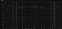
When I measured the left speaker (RED), I saw a lot going on around the crossover frequency (1650hz). Since I have these bi-wired, it was easy to reverse the polarity to the tweeter section. That measurement (GREEN) turned out to be much flatter. To my untrained eye, the tweeter section seems to be wired wrong.

Is that how others see it or is that how a properly wired RF-83 should look? Measurement was around 1 meter on axis.

Mike

RF83 Normal and Reverse Polarity.jpg
 
When I measured the left speaker (RED), I saw a lot going on around the crossover frequency (1650hz). Since I have these bi-wired, it was easy to reverse the polarity to the tweeter section. That measurement (GREEN) turned out to be much flatter. To my untrained eye, the tweeter section seems to be wired wrong.
Green certainly looks better.

Was the graph of the right speaker similar? What about if you reversed the polarity on it?
 
Green certainly looks better.

Was the graph of the right speaker similar? What about if you reversed the polarity on it?

The right speaker is tucked in a corner and hard to measure, but I reversed it as well.

First I think I'll do some exploratory surgery on the Left to see what's going on. Then I'll switch speakers so I can measure the other.

It's probably my imagination but they sound really good! I wish I would have measured them a long time ago.
 
Green certainly looks better.

Was the graph of the right speaker similar? What about if you reversed the polarity on it?

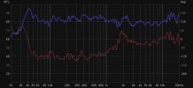
Since I found the carpet sliders, I went ahead and switched the speakers. The one that was on the right is now here the left one was and have measurements. I subtracted 20db from the plots of the second speaker so they stand out from the first speaker. The Purple is normal polarity, the Orange is with the tweeter polarity reversed.

Pretty much the same results. I keep wondering if I have the Bi-wire cables mixed up but can't see how. Next steps will be to plug the rear ports to see if that tames the 42hz bump. I've also wondered why the speakers sound so harsh at high volume, but that 10db bump sure looks suspicious. Perhaps a notch filter is in order?

RF83.jpg
 
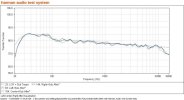
I would think the spl should be very slightly trailing off from 10k, Ala the Harman Room Curve, not doing the opposite.
image.jpeg
 
I've also wondered why the speakers sound so harsh at high volume, but that 10db bump sure looks suspicious. Perhaps a notch filter is in order?
What are you considering "high volume"? I know they are two different speaker systems but what is your comparison of the RF-83's vs K-Horn?
 
What are you considering "high volume"? I know they are two different speaker systems but what is your comparison of the RF-83's vs K-Horn?
All I can say is the louder I play them the more fatiguing they get.

As I understand it, the RF-83's have the K-71-G tweeter. I decided to pull it out and test it. There are no markings on it, including polarity, as far as I could tell. The negative wire was attached to the smaller of the two tabs, so I assume that was correct.

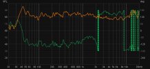
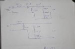
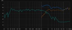
I measured the tweeter with no filter (Blue). Not pretty. I then measured it with the high pass filter (Orange). It's a third order that really slices through that initial bump. The filter also has a 4350hz notch to tame the second bump. Unfortunately, there's nothing to tame the final bump. I'm going to try a 220uh series inductor to tame that one.

The Green trace is the Woofer(s) response. It's around this area that it appears I have the polarity issue.

Doing my best to do justice to the thread title.

Mike

RF83 Schematic.jpg

RF-83 Tweeter.jpg
 
The Purple is normal polarity, the Orange is with the tweeter polarity reversed.

Pretty much the same results. I keep wondering if I have the Bi-wire cables mixed up but can't see how. Next steps will be to plug the rear ports to see if that tames the 42hz bump. I've also wondered why the speakers sound so harsh at high volume, but that 10db bump sure looks suspicious. Perhaps a notch filter is in order?

View attachment 2921492
To my eye, the measurements taken with the polarity reversed (i.e., the green and orange traces) look better in that the the dip around 1500Hz and the peak just after 2000Hz have been addressed. I would imagine that would be an audible improvement. Do th speakers sound less fatiguing when you listen with them wired in reverse polarity?

Since the original (red, purple) traces don't go past 5 kHz, we don't see how the HF (esp. above 12 kHz) compares for normal vs reversed polarity. However, looking at the filter vs no filter trace, I wouldn't expect there to be much difference

Were it me, I would adopt the new (aka reversed polarity) wiring.

Have you looked at the phase measurement of the different configs ("normal" and "reversed")? How do those graphs differ?
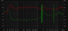
 
To my eye, the measurements taken with the polarity reversed (i.e., the green and orange traces) look better in that the the dip around 1500Hz and the peak just after 2000Hz have been addressed. I would imagine that would be an audible improvement. Do the speakers sound less fatiguing when you listen with them wired in reverse polarity?

Since the original (red, purple) traces don't go past 5 kHz, we don't see how the HF (esp. above 12 kHz) compares for normal vs reversed polarity. However, looking at the filter vs no filter trace, I wouldn't expect there to be much difference.

The original (red, purple) are both traces from 20hz to 20000hz. They just happen to overlay perfectly except for the crossover area.

Were it me, I would adopt the new (aka reversed polarity) wiring.

Have you looked at the phase measurement of the different configs ("normal" and "reversed")? How do those graphs differ?

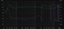
I looked at speaker A (red), forgot to look at speaker B (purple). Now wondering if only speaker A is wired wrong. I'm going to open it up today and see what's going on.

The red plot are speaker A normal.
The green plot is speaker A reversed.
The purple plot is speaker B normal.
The orange plot is speaker B reversed.


Speaker A Normal.jpg

Speaker A Reversed.jpg

Speaker B Normal.jpg

Speaker B Reversed.jpg
 
The red and purple plots look the same as do the green and orange, but the normal and reverse plots do differ with that peak @ 2.2kHz.
 
All I can say is the louder I play them the more fatiguing they get.
Recently, I retrofitted a (new) different tweeter to my Large Advent speakers. It sounds great, but as I started to turn the volume up I quickly realized (and/or forgot) that the speaker has severe limitations compared to my Heresy's or the all horn three way system. Power compression was very apparent at higher moderate volumes and everything just turned to mud.

The Advents sound great at low to moderate volumes and that is it. Still love them though for what they are.
 
All internal connections seem to be good. It's almost as if Klipsch purposely wired the two-way out of phase :dunno:

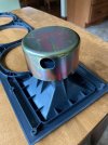
Took a picture of the tweeter. Can't tell if it's the same as the one Speaker Exchange says is the genuine K-71-G. That metal cover is crimped on so I can't remove it without bending tabs. Not sure why it's there to begin with.

Gonna just listen for a few days with the Tweeters connected out of phase.


KLIPSCH_1000329-2.jpg


thumbnail_IMG_0161.jpg
 
Measurements don't lie and if something doesn't look right, then it probably doesn't sound right.
 
Those measurements look like my LS when I reversed the phase on the tweeters.
There was a noticeable variance in the response around the crossover frequency.
 
Took a picture of the tweeter. Can't tell if it's the same as the one Speaker Exchange says is the genuine K-71-G. That metal cover is crimped on so I can't remove it without bending tabs. Not sure why it's there to begin with.
My guess would be it’s holding a bucking magnet in place?

Rf-83 are video shielded I believe
 
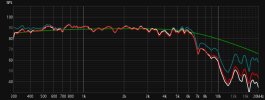
I think I have figured out how to apply a crossover slope to an actual measurement. This test was to simulate an ALK Universal squawker filter on a K55M.
I did a raw measurement of the K55M, starting at 300hz (Blue). I then used REW to generate a butterworth band pass...first order high pass at 400hz and second order low pass at 6000hz (Green). I then used Trace arithmetic to apply the voltage change of the filter to the raw measurement (White). Last I ran a sweep of the K55M using the ALK crossover (Red). To my surprise the simulated response (White) is very close to the real response (Red).

I wish I could enter inductor/capacitor values in the EQ function of REW, but hopefully this trick will come in handy someday???

Apologies to anyone who already figured this out :confused:

Mike

K55V Solder Real vs Simulation.jpg
 
Back
Top Bottom