• The move to the new server is done. There are some software and database maintenance updates in process. This has us passing the hat around to help out. We appreciate any donations. Seriously, even a dollar helps. The payment page may be found here - https://www.audiokarma.org/support.html

Mitsubishi LT-30 restoration

Many thanks for the info!

On thing though, the service manual says that the tracking servo can be adjusted by that covered up screw. You're saying that we shouldn't touch it?
 
Thanks for the bracket pic, Aerobat. That unit (your old one?) appears to be missing the sticker that covers the “on-off” adjustment. Maybe the early units (thats a low S/N) didn’t have it, and users mistakenly undid the screw while setting up the TA. Yikes!

That unit was in amazing shape, probably due to the original packing and bracket ! Finding one without damaged corners is almost impossible otherwise. There is another bracket, implied in the manual, on the side where the sticker would be, that somehow sticks a cushion pad under the TA (to get the nylon wheels off the rails, I assume). When last I moved, I cushioned the bejesus out of that area. Did that unit (if yours) also have the transformer immobilizing screw?

That's a pic I found somewhere on the Internet.
 
It is an adjustment, but not from the outside. The screw locks a fixed bracket in place that the microswitch actuates against as the TA rotates. You have to have access to the bracket, & hold it in place, while you tighten the screw. In the attached pic , in the lower right hand corner, you can barely see (I hope) the black bracket against the arm of the microswitch SS-5GL.
 

Attachments

  • 8467B075-B498-4146-A293-E489E009E8A2.jpeg
    8467B075-B498-4146-A293-E489E009E8A2.jpeg
    95.7 KB · Views: 43
BTW, in that same pic, the two slotted screws seen in the far lower right are the REST & SOR screws. The one closest to the chrome rail is the REST adjust. The other, SOR. They are covered when the TA is at rest.
 
Great, thanks. I don't suppose you have a photo of how the cam thing of the tracking angle screw adjustment works please?

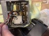
I had to do some digging but I found photos from when I replaced the tracking bulbs.

y4mbCrb0mMzXUqgs-BkMdZGPJHMj-bn4fmSwboPcij9DOajvhIi9tZLwxbBrh1sJkwJtjHBvSCTMDzUcIL4293nZKBe58E80YbDOoYNYIwrhlVMEN15iQd_w0AEUCao8uF4MruX8hmraNEjhTaM4HwTKJTIMuzpe0r5JPPTh9XZnEr3HNVEdAVOfoYboieQ4FNzgUQ85jBPjD1YvDmQH4Z2ag


y4mNZI4c_GcJm0TKFl8Zm0AZuUcdAMMLjhRp8CXO1AOGsaaShm3ZWiq_pHMfri0JTPXc2CU5EwzzKbZIla4nHP6QfuqY0RPLj60LTqJHg141WPBhoGUBNzsi59JYG2XT-SL7jpPHeJ7b6ITyXHLsGbFDt6ur17Ljqv8698zuTeRruN4CISIpirc0Dtw307Nga3lFeyoO9joLKZlI3tqwywuQg


As you can see the bulbs are in the black plastic ring with is held still with a spring. The tracking angle adjustment rotates this ring which changes the tracking as the computer aligns the bulbs with the sensors underneath.
 
Okay, this is what's happening to my deck at the moment. The tonearm isn't being dragged back or forth as the stylus hits anymore, but the arm still isn't tracking as the record is playing. The tracking error lights for both right and left are both on, without the middle bar coming up. I've no idea what this means.

I'm trying to adjust tracking angle as per the manual again. Using the printed alignment template, the tonearm angle does seem slightly off - there is an element of inaccuracy due to the paper, I need to print it on thicker card so that it doesn't bend and flop down as the sheet clears the vinyl. However, no matter which direction I turn the adjustment screw, nothing perceptible happens to the angles.

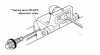
Finally, I know it's been said that the tracking servo adjustment screw is on the inside, but the service manual clearly shows an adjustment on the outside. I haven't tried to peel off the disc yet.

Screenshot 2020-07-23 at 12.22.25 AM.png 20200723_003835.jpg

I'll give it more attention at the weekend, but I may just have to give up and leave it for the repairman.
 
If your turning the adj screw and nothing is happening that’s the first thing to repair. Stated earlier, your going to need to remove the bottom at a minimum to see what’s happening when the screw is turned.
 
Cheers. I think so. probably best to leave it to a professional. Last time I tried to repair something , a sony TCD5 Pro, I made it worse.
 
Please remember that service manuals are written before the product goes in to production. Certain manufacturers will update and revise them as the product changes and issues are found and revised. Some are great at this. Mitsubishi is not one of them. The LT-30 SM is pretty bad and basic, as is the LT-20. At one time, that adjustment may have been the intended method and I have only worked 3 units (own 2) plus LT-20’s & 22, & LT-5. Maybe some one else will chime in with a better picture, of the screw & bracket, but on my units I did specifically look at that adjustment based on the same SM instruction in case it needed adjustment and all I’ve seen were still factory lock painted in place, so no adjustment required. If the sticker still covers the hole on yours (one of mine was half peeled off), then it is almost certainly correct. Also, the screw IS accessible (only) from the outside, under the sticker, but if your unit has a base colored sticker over it, I assure you it does not actually adjust anything except tighten the bracket down.

BTW, you do realize that the “on-off adjustment” does NOT refer to the horizontal movement itself on and off, but when the horizontal tracking as a whole is activated on or off. Tracking does not occur when the TA is cued up (OFF) or in the rest position. That adjustment switches it in when the TA is down in play only (ON). I realize I did not make that clear, earlier so it may have been confusing.

Both tracking bulbs on at the same time without the center “good” light, was addressed in a previous post somewhere, I recall reading it. I thought it meant both bulbs burnt out, but I remember it was resolved.

TA disassembly to that level is a royal PITA. It is not fun. Maybe for some but I found it annoyingly frustrating. You have to desolder the delicate cartridge wires from the mute switch, to get enough slack to pull the arm out. We all have/had pictures to make sure we get it back together because the SM is useless in that regard. Soldering fine TA wires is right up there with getting teeth pulled just about.

To see what the tracking screw does, requires total TA disassembly to the level shown In Aerobats photo. It just pushes by rotating the spring loaded (which is seen in the photo) bulb holder part relative to the brass post. The shutter is fixed such that neither bulb is revealed to the sensors in the exact center position.

 
Last edited:
Okay, I felt brave and decided to try and get the tonearm assembly off to see what the angle adjustment screw does. It was quite good fun, I got to photo 4 of post 2. I didn't get to Acrobats photo as I chickened out - the SM says that I had to remove E rings and screws. I did turn the angle adjustment screw and could see something at a deeper level move, and as you say it moves in a continuous cycle rather than having two extreme positions. I managed to put it all back and the turntable functions as before. Phew, no worse. Now I'll leave it to the repairman.
 
I am betting the bulbs are burnt out. Not sure where you are located, but whomever works on it, make sure they have done an LT-30 before!!
 
Back
Top Bottom