PART 2
It was this very scenario that led to the development of Enhanced Fixed Bias, or EFB(tm) some years ago, and it is just as effective with in the Magnavox chassis as it is with the small Dynaco amplifiers on which it was developed. A quick review of EFB operation might be helpful to those not familiar with it. Using EFB:
A. The tubes now operate under true fixed bias conditions, where the bias voltage applied to the tubes is independent of current flow through the tubes. As a result, bias voltage does not creep with the application of signal (hence, use of the term "fixed"), so an over-bias condition cannot occur.
B. But beyond simply creating fixed bias conditions however, once the quiescent bias is set to its optimum value, EFB then acts to maintain that optimum value, in spite of changing power supply voltage levels due to either changing AC line voltage conditions, or changing power output (i.e, current draw) demands from the amplifiers. This is far superior to traditional fixed bias, where changing plate and screen DC voltage levels cause the optimum bias setting to vary all over the place under changing dynamic conditions. It is also far superior to traditional screen grid regulation, where regulation of the screen is good, but if it is the only element regulated, while all the other element's DC levels are still varying, then its effectiveness is limited. It is the "Enhanced" portion of EFB that seeks to keep the control grid (and screen grid when necessary) in a
relative lockstep relationship with the plate supply voltage, regardless of how it might vary due to changing AC line or dynamic conditions. And, it is very simple to implement as compared to providing tightly regulated power supplies for each element -- and it produces the same low distortion level as the latter approach achieves as well. It is really a win-win situation, with no down side.
Applying EFB to the output stages of the 9300 then produces the following results, based on both channels being driven:
A. Power output in both channels is a sustained 15.5 watts RMS, representing over a 150% increase from that produced by the original design when both channels are driven. When only a single channel is driven, power output reaches 17.0 watts RMS -- this due to less drop in power supply voltages in this scenario.
B. Midband (1 kHz) THD easily drops to under 1% within 1 db of 15.5 watts power output (typically about .70%). In the stock design, notch distortion is just commencing at 1 db below the maximum power output of 10.24 watts, so distortion is significant (~ 2.8%). This means that the modified amplifier is producing less distortion on more power, than the original design is even capable of producing in this scenario. Forgetting the increased power for a moment then, distortion at the 1 db down points has been reduced some 75%.
C. Under quiescent conditions, each output tube idles at a phenomenally low total current draw of just 22 ma (44 ma per channel). Each tube now dissipates just 7.1 watts at the plate -- even less than in the original design -- which amounts to operating at 59.2% of the conservative Design Center rating for the tube (12 watts). This translates to a very long tube life indeed.
D. The operating temperature of the amplifier is notably reduced, particularly that of the power transformer. In combination with the buck connection supplying the correct primary voltage, the reduced heater current draw from using a GZ34 rectifier tube, and now the reduced quiescent current draw due to operating the output stages under the control of EFB, the power transformer reached a low 114F after 2+ hours of operation in a 68F environment. This too speaks to component life in a big way.
Finally, installing EFB of course caused all traces of the notch distortion that appeared in the original design to completely disappear as well.
A few pics are provided, but do remember that this is a development mule........
View attachment 648902
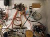
1. The entire EFB circuit easily mounts in the upper right section underneath the chassis. Also visible are the two 10 ohm common cathode resistors for each channel near the bottom center of the pic. Because the tab of the LM337 operates at ground level, no insulation kit is required, although a little silicone grease helps ensure a good thermal contact with the chassis. Under a worst case scenario (continuous full power output in both channels), the EFB regulator dissipates approximately 2.5 watts, which certainly works to ensure its own long life as well.
View attachment 648905
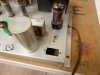
2. On the top side, the new bias control occupies the place of the old hum balance control. Down the road, the three terminals which are currently the speaker output connections will serve as the bias test points for each channel. Three terminals are required since the common connection in this application is not at ground level. Therefore, one terminal would be required to represent the meter common connection, while the other two would represent the test point for each channel. That way, the bias can be adjusted without having to turn the amplifier upside down to do it whenever the tubes are replaced.
View attachment 648909
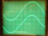
3. The two images are not calibrated the same for vertical gain so as to be able to show the complete waveforms. On the bottom, the stock design is operating in one channel (using a 200 ohm cathode resistor and bypass cap), and has not even reached the full power point where clipping commences (10.24 watts) and yet, notch distortion is clearly already evident. The top waveform is the other channel with the output stage operating under the control of EFB, developing over 16 watts RMS, as the onset of clipping is approached. Note that besides the increased power, the notch distortion is gone, yet the output tubes idle at an even lower level of quiescent current.
With the power supply and output stages addressed, the next installment will deal with the phase inverter, NFB, stability, and the output transformer.
Dave