• Please note that Audiokarma will be offline briefly for updates early on Monday morning, September 28th.

More Fun With Magnavox: The 9300 Series

Great technical breakdown. The 9300 series, like life itself, seems to impose compromises especially for owners of 8 ohm speakers due to output transformer design. Looking forward to the rest of the analysis.
 
Following along keenly, as I have a 9302 in the project queue. I'm assuming the 8802 would also benefit from the EFB treatment. How generic is the EFB circuit (i.e. how much change is generally required to the EFB circuit itself to move it to a different amplifier circuit)? Looking at your article on Tronola.com about EFB an SCA-35, it seems like the EFB circuit itself is very general and fairly easily integrated into any cathode-biased output stage.
 
Very little. The 9302-00 employs two small (100 pF) caps connected between pin #7 of each 6EU7 and ground to control the supersonic response of the unit. The 9302-10 omits these caps, and instead uses two caps of the same value connected between pins #8&9 of the same tube.

Dave
 
  • Like
Reactions: ewf
Dave , Thank you for your clear, step-by-step explanations, I learned a lot following this and a few concepts make more sense to me regarding plate loading.
I have a question concerning the implementation of EFB and how it allows the output stage to operate under fixed bias conditions. My understanding is that under fixed bias the grid leak resistors should be no more than 300k, does EFB allow for that to be exceeded or is that not a big deal? Does keeping it at 470k load the previous stage better? TIA
 
THE PHASE INVERTER, FREQUENCY RESPONSE, STABILITY, AND OTHER STUFF.........

This part of the project starts -- once again -- with the output transformer, as it determines so much of the performance outcome of any feedback amplifier.

The original 9300 design operates with 12 db of NFB, which proved to be right at the maximum amount of NFB that the OPT can handle if HF stability is to be reasonably maintained. Greater amounts of FB produced poor stability with speaker loads, while any reduction in FB hurt distortion, frequency response, and increased output impedance. So 12 db proved to be the optimum level for the transformer, which is the amount that Magnavox used, and I continued to use throughout the project.

With this relatively small amount of feedback, the transformer's resonance characteristic causes a significant amount of ringing to appear on square waves that cannot be tamped down by the usual method: Ergo, there is no feedback cap across the feedback resistor in any of the 9300's offerings. In fact, the use of any such cap seriously compromises HF stability in this design. But left unchecked, the resonance characteristic that all OPTs have makes for a rising HF response characteristic right up to the transformer's resonant frequency under feedback conditions. Besides this undesirable outcome, the complex load that a speaker represents can then take this response pattern, alter its phase as a FB signal, and change it from a negative one to a positive one at supersonic frequencies. Helloooo instability!

In the best designs, the OPT's resonance is pushed to such a high frequency, that amplifier response can be controlled to remain well under that frequency, while the effects of that control still all occur safely above the upper portions of the audio band. This leaves response at the higher audio frequencies (up to 20 kHz) ruler flat, with all the other benefits of NFB in place throughout the audio bandwidth as well, and the amplifier relatively insensitive to speaker loading with regards to HF stability. Buuuuut, that's not what we're dealing with here. The resonance and phase shift characteristics of the 9300's transformers are such that both basic frequency response and power transfer capabilities are well compromised down into even the mid-range audio frequencies (above 1 kHz), so that any remedies for improvement must be well tempered, save the medicine becoming worse than the disease. So what to do?

Magnavox dealt with the rising response issue by limiting the HF response of the phase inverter stage -- the normal way such a goal would be approached. This was done by way of the 47K input grid resistor for the AF amplifier section of the 6EU7, the use of relatively high value plate load resistors for both sections of that tube, and (when installed) those little 100 pF caps that were connected to either the plate or grid elements of the AF amplifier stage. Together, these measures were meant to counter the rising response created by the use of 12 db of uncompensated NFB around the 9300's OPTs. But without any active HF corrective action around the entire amplifier that is a form of NFB itself, it leaves both the AF Amplifier/Phase Inverter section and the output stage section operating quite independently of each other, with therefore nothing to account (HF wise) for variances in tube characteristics, component tolerances, or slight differences in wiring layout. To that point, this is a significant part of what a traditional small cap across a NFB resistor accomplishes -- except that form of compensation can't be used here. Additionally, beside the measures already mentioned to control the response of the AF Amp/Phase Inverter section, one other measure of control was used as well: The inherent frequency imbalance that occurs between the outputs of a Paraphase type inverter circuit.

Within the hierarchy of phase inverter circuits, the paraphase inverter design -- as used in the 9300 -- is a bottom feeder: There is precious little within the design that acts to maintain an equal balance between the two outputs with regards to either frequency response, or component variations. As a result, while the balance can be made to be generally accurate at mid-band frequencies, as the frequency varies either way, the effects of Miller in the inverter section on the high end, or the additional (bottom) coupling cap on the low end really cause the imbalance to grow as frequency deviates above or below the mid-band range. Either way, the response in the bottom output leg becomes rolled off as compared to that from the top. Also, even with mid-band balance established, that can be upset with component or tube changes over time. As a phase inverter, it does work. But for high quality applications, it only works after a fashion, having little to hang its hat on. In any event, it is the inherent HF roll-off in the inverter section of this inverter that Magnavox was counting on to help control the rising response produced by the uncompensated feedback network.

With the deck stacked against this type of inverter then, and the lack of any active HF NFB compensation, it's no wonder then that HF transient performance was poor, HF stability was marginal, distortion due to frequency imbalance high, and overall frequency response anything but flat. The results of this design approach are all well depicted in the base line data, and in the square wave pics presented. But remember, this was designed for an economy console setting. There were no long speaker cables or complicated crossover networks to upset stability, speaker networks could be tailored to account for amplifier response, and tone controls were likely set at anything but flat in the system anyway. At the moderate output levels the unit was was designed to operate at, the sound produced was no doubt enjoyable, so it's doubtful that anybody was really concerned about the limitations of the design. These consoles were all about enjoyment of rich velvety sound rather than high fidelity accuracy. Today however, these amplifiers are now operating in stand alone settings, often driving high definition speakers of which each speaker new alone cost more than the whole console did in equivalent dollars back in the day, with long speaker cables and potentially high capacitance loads, amplifying recorded music with more dynamic range than its designers could ever dream of. Today, the spotlight on these amplifiers is focused and bright. It is that reality then that drives the effort to raise things up a tick.

To that end, along with the modifications to the power supply and output stages, the original phase inverter has now been modified as well, with more gain, a new NFB and HF stability arrangement, and greatly improved frequency balance, which all work together to produce lower distortion, improved stability, and a flat frequency response, and which are now well maintained regardless of tube characteristics and/or component tolerances. At this point then, all this has been accomplished by way of circuit design changes alone, while still maintaining the original building blocks of the 9300 amplifier: The chassis and it's transformers. Down the road, new OPTs will be considered, as that is now the only thing standing between current status, and a really high ranking performance wise. With the modifications developed, the amplifier is now worthy of whatever OPTs you might want to put into it. But that's down the road. For now, this is going to be a temporary soft landing point until other projects and family needs can be attended to. For the 9300 however, it's really a great place to land: costs for the modifications are low, they are easy to perform, and the return is high. With the table fully set then, I hope to have the schematics posted tonight, showing how all the issues of the 9300 have been dealt with.

Dave
 
Waiting with baited breath to see what you came up with. I'm going to count the slow progress on my Maggie Console Rebuild as a fortunate stroke of luck. I've been happy thus far with the results my reading, inquiring and oscillo-ears have produced, but it will be very nice to have your expert appraisal of these amps as a guide to help complete my project. I think we all appreciate it when individuals such as yourself with the skill and equipment take the time to share your expertise.
 
Once again, I have to offer a thanks for your efforts on all this. I've sort of been meaning to get back to my own 9300, and this will give me motivation. Its been on the shelf a long while because I've been a bit underwhelmed with it compared to some of my other stuff. It has other output transformers, but previously I never had any test gear to really see what it was doing, and frankly not enough understanding to know what I was doing anyway. I have half of that sorted, test gear you can buy :) Anyway, I plan to implement some of the awesomeness from this thread on what I've got and see what it gets me. I'm hoping for magical things.
 
WRAP UP -- Part 1

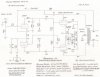
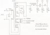
The modified circuits of the 9300 are posted here, with the following notes and features:

POWER SUPPLY:

This remains relatively unchanged except for five basic points:

1. The extra tuner heater winding has now been configured in an autotransformer connection with the primary winding to reduce the voltage applied to the primary winding to 115 vac, which is the design center voltage for this winding. Voltage applied to the heaters is now within 2% of the target value with typical line voltages of 121-122 vac.

2. The hum pot has been eliminated, and balance resistors used in its place. Use of a hum pot in a basic power amplifier setting typically offers little practical advantage.

3. The rectifier tube has been changed to use a 5AR4.

4. The voltage supply points are re-labeled for the correct modified values, which includes a new dedicated output tube screen grid supply point.

5. A 2A fuse and power switch is included for practicality and safety.

Comment: Because this is a development model, the original good can cap is still in place and in use, providing good service. As a result, the 10 uF section originally used to decouple the phase inverter stage is now used to decouple the screen grids, with a new discrete decoupling cap added to decouple the phase inverter stage. Because the screen grid decoupling cap is so small, no Screen Stability resistors were required in the development model, and are not shown in the pic provided. However, they ARE shown on the amplifier page, since any unit destined for regular service will almost certainly have the can cap replaced, with 40-50 uF being a good practical value to use at this point. With such a value, Screen Stability resistors will be required, and are therefore shown on the schematic.

These changes, along with those made to the output stages, now have the power transformer operating at a very cool temperature. After three hours of use in an open 68F environment, the transformer failed to even reach 120F. With typical power transformer operating temps of 140F or so, this sucker is one cool cookie indeed.


AMPLIFIER:

While the basic topology remains the same, important changes have been made that really improves overall performance significantly. These include:

1. OUTPUT STAGE: Operation of the output stage has been modified to use a simplified form of EFB(tm) for pentode operation. In this scenario, no negative fixed bias supply was readily available, so an EFB cathode regulator was used to provide true fixed bias operation. However, with the advantage of the "Enhanced" element that EFB provides, the optimum operating point is always maintained under all conditions of operation, in spite of power supply fluctuations due to AC power and changing dynamic conditions. This is important, as when the amplifier is developing full power into a 4 ohm load in both channels at the same time, the power supply requirements increase from about 90 ma under quiescent conditions, to nearly 200 ma with 15.5 watts RMS being developed in both channels at once. This causes the B+ to the OPTs to drop some 40 vdc -- and importantly, the screen grids by about 50 volts. This would normally produce a significant shift in the operating point, and greatly increase distortion. But because the EFB cathode regulator controls the bias to the tubes -- which is based on the screen grid voltage supplied to the tubes -- the bias is automatically adjusted accordingly, and maintains the optimum operating point regardless of what the B+ voltages are. The only way that this low distortion performance can be matched with traditional absolute regulation, is to regulate ALL grid and plate potentials, which is an expensive proposition to produce. Also, because the loading conditions require the screen grids to operate at nearly the same DC potential as that of the plates, a simple dropping resistor for the screen grids can be used to power them, with little loss of regulation: Of the 50 volts that they drop in operating voltage between quiescent and full power, only 10 of those volts is due to the dropping resistor, which is rather insignificant. Ultimately however, it matters little, since the EFB arrangement accounts for the full drop in screen voltage under large dynamic conditions.

Now besides completely eliminating the notch distortion and greatly reducing THD in general as discussed in the setup posts, the other huge benefit of EFB operation is that the optimum quiescent operating point of the tubes now falls to just 22 ma per tube, or 44 ma per channel. This means that each tube is dissipating just 7 watts at the plate, or less than 60% of the tube's conservative Design Center rating for plate dissipation. This equates to extremely long tube life -- and the cooler power transformer operation. It is also the reason that in spite of the autotransformer connection of the power transformer's primary winding, the lower quiescent current draw and use of a low drop 5AR4 rectifier tube cause the quiescent B+ voltages to rise to higher than normal levels (although the turn on surge is completely eliminated). But this is of little concern, as maximum voltage ratings for vacuum tubes can -- and are -- often exceeded, which can be very safely done -- as long as the tubes are not operating at or near rated dissipation levels. With the very low dissipation levels in this amplifier, the 6BQ5/EL84 output tubes used showed absolutely no signs of concern, and in fact are operating under much less stress than if only 300 volts were applied to the screen and plate elements, but the tubes idled at 35-37 ma each, as is customary in most traditional cathode bias settings. In this amplifier, as the production of power is elevated, the operating voltages will fall as discussed, so that even under full power conditions, the ratings for the tubes are not exceeded. Therefore, the modified design will work just fine with any version of the 6BQ5 family of tubes you wish to use.

End Part 1. Part 2 will be along shortly.
 

Attachments

  • SAM_1608.JPG
    SAM_1608.JPG
    124.6 KB · Views: 2,163
  • SAM_1606.JPG
    SAM_1606.JPG
    66.6 KB · Views: 1,692
  • SAM_1607.JPG
    SAM_1607.JPG
    66.2 KB · Views: 1,596
  • SAM_1609.JPG
    SAM_1609.JPG
    82.5 KB · Views: 1,954
  • scan0002.jpg
    scan0002.jpg
    79.2 KB · Views: 2,492
  • scan0003.jpg
    scan0003.jpg
    54.6 KB · Views: 2,494
WRAP UP -- PART 2

2. PHASE INVERTER: The phase inverter stage has been modified to operate as a floating paraphase inverter now, as opposed to the simple paraphase design originally used. This was done by making the grid return resistor of the top output tube slightly smaller than that for the bottom tube, and instead of returning the bottom tube's grid return resistor to ground, returning it to the junction of the two resistors that normally comprise the voltage divider making up the grid return resistor package for the top tube in a traditional paraphase design. This forms a NFB connection for the inverter section that provides a number of benefits:
1. The gain of the inverter section remains much more constant in the face of tube and component tolerance variations.
2. The two outputs from the inverter are now well matched over a wide frequency range, since the feedback compensates for both Miller at HFs, and the phase shift contributed by the "extra" coupling cap at LFs, that the bottom output tube sees but the top one otherwise does not.
3. The configuration is much more stable than the traditional paraphase design is with regards to LF stability. As a result, both coupling caps can be made the same value when using a floating paraphase design.
The opportunity was also taken to increase the gain of the phase inverter stage over that used in the original design. Since the overall global NFB used remains unchanged, this then translates into increased input sensitivity (now just .60 vac for full power output), which may be of benefit to some. For those who wish to maintain the original sensitivity level of 1.0 vac, a compensated reduction network is shown on the schematic that should be inserted between the input jack, and the junction of the 47K/470K resistors.
3. NFB/STABILITY: The approach to stabilizing the NFB employed now includes a new active HF compensation loop in the form of a 47 pF cap connected between the plate of the top output tube, and the NFB insertion point at the cathode of the AF amplifier stage. With this additional loop in place, the overall closed loop gain of the entire amplifier is actively controlled at HFs, and since the OPT is not included in this loop, it effectively reduces the HF response of the amplifier so as to be under that of the resonant frequency of the OPT, and thereby eliminating the ring associated with the original design. Used in conjunction with a new step network added to the plate of the AF Amplifier stage, HF stability is greatly improved, with the amplifier now being able to handle capacitive only loads of at least .03 uF. Also, with the dual feedback loops, frequency response is no longer elevated above 10 kHz as in the original design, but now down just .25 db at 20 kHz.
On the low end, the coupling caps have been chosen to intentionally limit response below 40 Hz, so as to minimize saturation of the OPT. But even at this, response at 20 Hz is down only 2 db, being 1 db down at 40 Hz. This represents better than an order of magnitude improvement over the original design, and response that is still better yet than those modifications that use .01/.1 combinations with the stock design. This is possible because of the improved LF stability that the floating paraphase inverter design offers, with the amplifier still showing rapid settling under pulsed conditions.
OVERALL: The modifications presented take what was clearly an economy console amplifier (selling point: Includes Dual Push-Pull Amplifiers!), and turn it into a solid stand alone contender. For 4 ohm loads, real usable power output has now been increased by just over 50%, while distortion within 1 db of full power output has been reduced 10 fold due to the elimination of the notch distortion present in the original design. Even with 8 ohm loads, power output is increased nearly 19% now, with 11.0 watts available at mid frequencies with both channels driven. In short, there is now more usable power output available at 8 ohms with both channels driven, and at greatly reduced distortion, than there was with the original design properly loaded at 4 ohms. 8 Ohm loading also extends the transformer limited power bandwidth of 4 ohm loading (40 Hz to 10 kHz) very nicely, to 35 Hz to 17 kHz when loaded with 8 ohms, although THD with 8 ohm loads is typically double that of 4 ohm loads due to the less desirable load conditions this presents to the output stage. Still, all distortions are but a fraction of that produced by the original design regardless of loading conditions. As well, frequency response is very flat now, while the stability of the amplifier is now completely appropriate for use outside the confines of a console setting. When amplifier power is increased, distortion reduced, response flattened, and stability enhanced, it translates into an improved listening experience across the audio bandwidth. The amplifier now demonstrates notably improved dynamics and clarity, and presents itself with a sound of quality belying its humble beginnings. As mentioned earlier, the only thing standing between this amplifier now, and running with the best of the EL84 pack, are the OPTs. But as is, it will now stand head and shoulders above all the "also rans" in the economy console class offerings.

Comments that support the pics (that somehow ended up in part 1!)

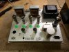
651553 Except for the addition of the fuse and power switch (external during development), here is the final build of the unit. As mentioned, there are no Screen Stability resistors installed in this mule yet, but will be once the can cap is replaced.

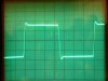
651554 10 kHz square waves are still display a slow rise time indicating the reduced supersonic response of the original OPTs, but note they are quite civilized now compared to that from the original design. And......

651556 For this amplifier, 2 kHz square waves tell a great story, indicating a very flat response up to 20 kHz, and a complete absence of ringing across the top and bottom of the waveform. This is NOT console performance.

651557 Other than the missing Molex plug, about the only change top side is the change in rectifier tubes, although the addition of a fuse and switch will change that slightly. The new bias control now resides where the old hum balance control did.

So there you have it as it stands for now. The schematics are intended for anyone to use for their personal enjoyment, and please respect that EFB is a trademark of D Gillespie Designs. For those of you who build the modified amplifier, I think you will be rewarded, and your comments are encouraged!

Happy listening!

Dave
 
awesome, thanks for the explanation on the inverter. I was thinking that it looked like paraphase with direct coupling. Is that the typical hallmark of a floating paraphase design then? Phase inverter theory is not something I've ever really looked into in any significant way.

One question regarding the EFB reference voltage source. Is there any reason this could not be connected to the B+ tap feeding the plates? Asking because my particular amp is set up to run ultralinear at the moment, so no screen supply. I can re-wire it pentode and I might at some point but I'd like to try it out both ways if I can.
 
Gadget -- The hallmark of a floating paraphase inverter is how the input to the inverter section is handled. That is, it is not locked to a predetermined attenuated signal from the AF Amplifier section, as it is in a straight paraphase design. Rather, that input is allowed to "float" to the correct signal level, as determined by the ratio of the two grid return resistors feeding the inverter grid. Once set for a balanced output, that balance tends to stay balanced regardless of changes in the gain of the inverter section: As the gain of that section goes up, so does its output, which then supplies a greater countering signal against the primary signal from the AF Amplifier stage, reducing the signal applied to the inverter grid. The result is that the output from the inverter section goes down to meet equilibrium again. If the gain of the inverter section goes down, then the opposite happens, again, achieving equilibrium in the output. For such a simple change, it really is a very much improved inverter design.

As for the EFB "sensing" connection, in a pentode configuration, it is the screen grid voltage that determines the maximum current draw that a tube can pass. Therefore, it not only acts in helping to establish what quiescent current is drawn for a given negative grid bias applied to the control grid, but also establishes the load optimum load impedance for the plate to operate into as well for a given plate voltage. Therefore, the voltage applied to the screen is critical, relative to the plate and control grid that it works in conjunction with. As a result, the voltage to it is what is sampled for the control grid regulator to take its queue from. With UL, it is the voltage applied to the CT of the OPT that is sampled for EFB.

I hope this helps!

Dave
 
So just so I can get my head around this, the floating paraphase floats because of the common cathode resistor vs independant? So in effect it sort of works like a common cathode does on an output stage, using one tube section to regulate the other ? This is opposed to the stock setup where you've effectively got two triodes operating independant of one another, and relying on the particular tube to be reasonably matched to the original design standard tube to maintain balance, meaning one "hot" section could unbalance the thing and you'd end up with uneven grid drive to the output stage.


**edit** looking into this further, I think I might possibly understand now. Instead of the inverter grid being driven off a voltage divider to ground, its a divider from plate to plate. That would let it somewhat self-correct since it would alter the grid bias on the inverter section with variations in tubes rather than just being fixed to a point.


Also I suppose it removes a possible phase shift point since you're losing a coupling cap from output tube grid back to inverter grid.
 
Last edited:
Thanks very much for all that Dave! Fantastic work again!

Is the PS 300-0-300 ?

Which in listening do you prefer the Floating Paraphase or the Cathodyne? That might be
hard to answer1
 
It is the grid of the inverter section that floats -- and it does so according to the balance of the two signals it receives from the two outputs of the section. By floating, it can then keep the two outputs constant in spite of any fluctuations in the gain of the inverter section.

Dave
 
Sorry for my ignorance of these tube circuits. Just a couple questions...
1. On the amplifier schematic, the output of the LM337 points "TO OTHER CHANNEL". Where on the other channel?
2. Are all 4 6BQ5 pin 3's tied together?
 
Back
Top Bottom