

You are using an out of date browser. It may not display this or other websites correctly.
You should upgrade or use an alternative browser.
You should upgrade or use an alternative browser.
More Fun With Magnavox: The 9300 Series
- Thread starter dcgillespie
- Start date


Morrism -- You know the old saying -- the only bad question is the one that wasn't asked!
In each channel, pin 3 between the two output tubes is connected by a jumper, therefore, two jumpers. Then, from each channel's jumped cathode terminals (pin 3), there would be a 10 ohm resistor connecting jumpered pair to the output of the EFB regulator. Therefore, at the output of the regulator, that connection includes:
1. One 10 ohm resistor to one channel's jumped cathode terminals,
2. One 10 ohm resistor to the other channel's jumped cathode terminals,
3. The 20 uF bypass capacitor, and
4. The two 220 ohm resistors from the heater winding.
Therefore the four cathode terminals are not all connected together, but connected together in two pairs, two for each channel.
Kevin -- I was really trying to stay within the boundaries of the topology that the original design represented. There are soooo many 6BQ5 designs out there that use the AF Amplifier/Cathodyne formula, that I thought it would be nice to stay a little truer to the original format. But in doing that, the original paraphase inverter needed so much help, that the logical move was just to modify it to the floating paraphase type. It represents a significant improvement over the original design.
Thanks for following along!
Dave
In each channel, pin 3 between the two output tubes is connected by a jumper, therefore, two jumpers. Then, from each channel's jumped cathode terminals (pin 3), there would be a 10 ohm resistor connecting jumpered pair to the output of the EFB regulator. Therefore, at the output of the regulator, that connection includes:
1. One 10 ohm resistor to one channel's jumped cathode terminals,
2. One 10 ohm resistor to the other channel's jumped cathode terminals,
3. The 20 uF bypass capacitor, and
4. The two 220 ohm resistors from the heater winding.
Therefore the four cathode terminals are not all connected together, but connected together in two pairs, two for each channel.
Kevin -- I was really trying to stay within the boundaries of the topology that the original design represented. There are soooo many 6BQ5 designs out there that use the AF Amplifier/Cathodyne formula, that I thought it would be nice to stay a little truer to the original format. But in doing that, the original paraphase inverter needed so much help, that the logical move was just to modify it to the floating paraphase type. It represents a significant improvement over the original design.
Thanks for following along!
Dave

Leland47
Super Member
Dave, I was looking at the specs for the 5AR4 compared to the original rectifier tube...the 5U4GB....and they don't seem that different ...to me. ( of course I know so little about all this....)
Could you elaborate on the specific reason you switched to the 5AR4?
Don't know the reason...but prices for a 5AR4 are much higher than for a 5U4GB...
Thanks...
Lots for me to study here.
Could you elaborate on the specific reason you switched to the 5AR4?
Don't know the reason...but prices for a 5AR4 are much higher than for a 5U4GB...
Thanks...
Lots for me to study here.

Morrism
Active Member
One more question. Are all capacitor values in uF? In particular there is a 47 on the amp schematic and a 56 on the input sensitivity reduction network.
Are all resistors 1/4 W unless noted otherwise?
oops.. that was 2 questions.
I'm putting together a Mouser order for the parts I need.
Here are some pics of my 9302.
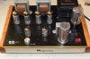
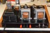
Are all resistors 1/4 W unless noted otherwise?
oops.. that was 2 questions.
I'm putting together a Mouser order for the parts I need.
Here are some pics of my 9302.
Morrism -- Correct -- the 47, 390, and (optional) 56 capacitors are pF values, and yep, 500 volt rating is in fact just dandy. You can use 1/4 watt resistors for the 10 ohm cathode and 100 ohm screen grid output stage resistors, and even for the 220 ohm heater balancing resistors. Using 1/2 watt resistors in the phase inverter section will ensure the lowest noise performance.
Leland -- The 5U4GB is a quick heating (employing no cathode) type of rectifier tube, that begins to conduct literally in a matter of 3 seconds or so. Since this is well before the audio tubes heat up and begin to draw current, the initial B+ at turn on rises very high -- to over 400 vdc, which is why an amplifier that was designed to originally operate at 300 vdc required 450 volt filter caps -- to handle the turn on surge. But also however, the 5U4 produces a rather high voltage drop across it, which only grows when power output is increased. So in effect, when you don't want the voltage, it's too high, and when you do want it, it's too low.
Against that backdrop, the 5AR4 is a much improved rectifier tube. It is a slow heating cathode type rectifier tube, so the turn on surge is completely eliminated. As the tube warms, the audio tubes are also nearly warmed, so there is no voltage spike. But also, the voltage drop produced by the 5AR4 is greatly reduced over that of the 5U4. This tends to make general voltages higher, but neither will they drop as much when extra current is needed by the amplifiers, either. This allows the amplifiers to put out more power with less distortion, since the regulation of the power supply is better. It also requires less current to power its heater as well, so it is simply a better tube all the way around for the application. At the time the console was produced, the 5AR4 was a relatively expensive tube, compared to the dirt cheap 5U4. The bean counters will always win that game.......
Kid -- No facilities have been provided yet on the development mule, but the readings are taken across the 10 ohm cathode resistors in each channel. Since they are not grounded, three test points will be required -- two for the output tube cathode connections (one for each channel), and one for the common point at the output of the EFB regulator where the cathode resistors tie together. Test points are something I'll leave up to the discretion of each builder.
Dave
Leland -- The 5U4GB is a quick heating (employing no cathode) type of rectifier tube, that begins to conduct literally in a matter of 3 seconds or so. Since this is well before the audio tubes heat up and begin to draw current, the initial B+ at turn on rises very high -- to over 400 vdc, which is why an amplifier that was designed to originally operate at 300 vdc required 450 volt filter caps -- to handle the turn on surge. But also however, the 5U4 produces a rather high voltage drop across it, which only grows when power output is increased. So in effect, when you don't want the voltage, it's too high, and when you do want it, it's too low.
Against that backdrop, the 5AR4 is a much improved rectifier tube. It is a slow heating cathode type rectifier tube, so the turn on surge is completely eliminated. As the tube warms, the audio tubes are also nearly warmed, so there is no voltage spike. But also, the voltage drop produced by the 5AR4 is greatly reduced over that of the 5U4. This tends to make general voltages higher, but neither will they drop as much when extra current is needed by the amplifiers, either. This allows the amplifiers to put out more power with less distortion, since the regulation of the power supply is better. It also requires less current to power its heater as well, so it is simply a better tube all the way around for the application. At the time the console was produced, the 5AR4 was a relatively expensive tube, compared to the dirt cheap 5U4. The bean counters will always win that game.......
Kid -- No facilities have been provided yet on the development mule, but the readings are taken across the 10 ohm cathode resistors in each channel. Since they are not grounded, three test points will be required -- two for the output tube cathode connections (one for each channel), and one for the common point at the output of the EFB regulator where the cathode resistors tie together. Test points are something I'll leave up to the discretion of each builder.
Dave

Morrism -- Correct -- the 47, 390, and (optional) 56 capacitors are pF values, and yep, 500 volt rating is in fact just dandy. You can use 1/4 watt resistors for the 10 ohm cathode and 100 ohm screen grid output stage resistors, and even for the 220 ohm heater balancing resistors. Using 1/2 watt resistors in the phase inverter section will ensure the lowest noise performance.
Leland -- The 5U4GB is a quick heating (employing no cathode) type of rectifier tube, that begins to conduct literally in a matter of 3 seconds or so. Since this is well before the audio tubes heat up and begin to draw current, the initial B+ at turn on rises very high -- to over 400 vdc, which is why an amplifier that was designed to originally operate at 300 vdc required 450 volt filter caps -- to handle the turn on surge. But also however, the 5U4 produces a rather high voltage drop across it, which only grows when power output is increased. So in effect, when you don't want the voltage, it's too high, and when you do want it, it's too low.
Against that backdrop, the 5AR4 is a much improved rectifier tube. It is a slow heating cathode type rectifier tube, so the turn on surge is completely eliminated. As the tube warms, the audio tubes are also nearly warmed, so there is no voltage spike. But also, the voltage drop produced by the 5AR4 is greatly reduced over that of the 5U4. This tends to make general voltages higher, but neither will they drop as much when extra current is needed by the amplifiers, either. This allows the amplifiers to put out more power with less distortion, since the regulation of the power supply is better. It also requires less current to power its heater as well, so it is simply a better tube all the way around for the application. At the time the console was produced, the 5AR4 was a relatively expensive tube, compared to the dirt cheap 5U4. The bean counters will always win that game.......
Kid -- No facilities have been provided yet on the development mule, but the readings are taken across the 10 ohm cathode resistors in each channel. Since they are not grounded, three test points will be required -- two for the output tube cathode connections (one for each channel), and one for the common point at the output of the EFB regulator where the cathode resistors tie together. Test points are something I'll leave up to the discretion of each builder.
Dave
Dave not to nit pick too much. But 5AR4's still sell at a premium compared to 5U4GB's

That being said I am totally with you on the reasoning behind switching from the 5U4. The power transformer thinks so also.
Frannoe

ferninando
Lunatic Member
AES has 5ar4 JJs rite now pretty cheepabout $13 ,sovteks $18 or 19
I just found one in my stash, amperex, so Im good to go.
I just found one in my stash, amperex, so Im good to go.
AES has 5ar4 JJs rite now pretty cheepabout $13 ,sovteks $18 or 19
I just found one in my stash, amperex, so Im good to go.
Hiya,
Yep I know "New Production" are comparable.
But you can find nice NOS 5U4GB's for this type of price. Not so with NOS 5AR4's.
Good find on the Amperex. That should last a lifetime

Frannie
BrokenHill
Well-Known Member
Would there be a problem using the newer made tubes over NOS or good used old 5AR4 tubes ?
maybe they don't last long.
maybe they don't last long.
Would there be a problem using the newer made tubes over NOS or good used old 5AR4 tubes ?
maybe they don't last long.
ACK!!!
OK ... lets take this somewhere else as what tube is better is not what this thread is about.
I apologize Dave and others ... that was a attempt at mild humor on my part.
Frannie
ferninando
Lunatic Member
Both new and used are perfectly OK IMO. Just as good as nos performance wise.
I am gonna get hit for that .
so be it.
I am gonna get hit for that .
so be it.
BrokenHill
Well-Known Member
I have seen the threads about how different rectifier tubes are said to affect the sound, I really don't
much about that because I never tried any of the newer brands.
I have also heard that the newer tube brands just don't last as long, I would tend to believe that.
I would be willing to try one of the newer 5ar4 tubes that AES has if it's just a longevity problem,
the cost of the tube at AES is okay with me.
much about that because I never tried any of the newer brands.
I have also heard that the newer tube brands just don't last as long, I would tend to believe that.
I would be willing to try one of the newer 5ar4 tubes that AES has if it's just a longevity problem,
the cost of the tube at AES is okay with me.

This amp really should not heavily tax a rectifier, so I would expect a new production to handle the task fine. I've got 3 new Sovteks in service in more demanding applications and all are doing OK. Some of that short life thing has to do with amps that beat the snot out of the rectifier, and this ain't that.

Harlon
Active Member
Dave,
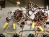
Could you take a pic focusing on the phase inverters, framing in from the coupling caps upwards? I tend to learn best by walking myself through the schematic and comparing it to what I see in the physical form. It may be my iPad, but when I try to pull in on the 6EU7s to work out all the resistors and such everything just a starts to blur together.
Much appreciated,
Thanks,
Could you take a pic focusing on the phase inverters, framing in from the coupling caps upwards? I tend to learn best by walking myself through the schematic and comparing it to what I see in the physical form. It may be my iPad, but when I try to pull in on the 6EU7s to work out all the resistors and such everything just a starts to blur together.
Much appreciated,
Thanks,
Hope this helps! And contrary to my previous comment, you can use 1/4 watt resistors for the cathode components and the step networks as well.......
Dave
Dave
