• Check out the Annual AK Secret Santa exchange Program, signup before November 23rd in the AK Charities & Christmas forum!

MX-110 model identification and restore...

Done. My Mouser parts came in today, the filament PS caps and the 12uF 250V cap. Will do the PS caps first and look to see if I need to wait until later to do the 12uF/250V cap because of space considerations....

Untitled by analog addict, on Flickr
 
Got the filament power supply finished up.

Untitled by analog addict, on Flickr

Again compared to my previous work over 10 years ago, I think it's a step up...

Untitled by analog addict, on Flickr

Needless to say, I think I'll redo some of my old work when I finish this one. Rest of the parts came in this afternoon, so I'll be trying to really get going on this shortly...
 
Again very nice work! If I may however, let me draw your attention to one correction that needs to be made:

In the Pic of the unit you are currently working on, please look at the black 2000 uF 16 volt cap (C117B), and in particular, it's negative lead. It is currently grounded at a ground tag on the tube socket for V8, which is in error.

The negative side of the DC heater supply of the MX110 is biased above ground by some 83 vdc. As currently connected then, when power is applied, the circuit would be attempting to place a voltage across this cap equal to the bias voltage plus the 12.6 vdc of the heater supply, or about 95 vdc. This would ultimately either ruin the cap, burn out R153, or both rather quickly. The negative lead of C117B needs to be connected to a ground tag on the old DC heater can cap, since it appears you are still using it as the negative side of the DC Heater supply. Note the can is mounted on an insulated mounting wafer, with the can itself employing a cardboard cover, precisely because the heater system is elevated above ground.

Your current work is a nice step up!

Dave
 
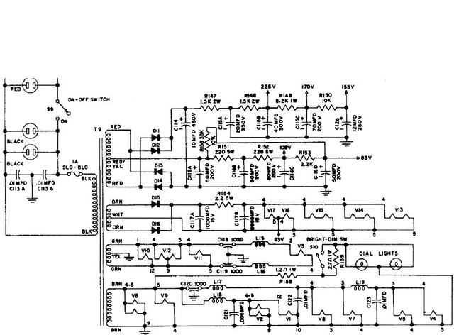
Thanks Dave. I was wondering about the schematic and mistook how that 83V was connected since they don't use a dot/node at that connection. Can you tell me what the 4 and 5 numerals are indicating? Thinking about it, are those pin connections for the individual tube's filament supply? Series for the 12V filaments and parallel for the twin triode 6.3V filaments?
 
Yes, those are the terminal numbers at the tube socket for each tube shown. V13, V14, & V15 are the 12AX7 tubes, with the heater power connected to pins 4&5 at each tube. These are the 12.6 volt heater connections for these tubes, which is the way they are operated in the MX110 (6.3 volt operation of these tubes would require pins 4&5 to be connected together, and the power applied between these two pins, and pin 9).

V16 & V17 are the two 6U8 line stage tubes, and because the heaters in these tubes run off 6.3 volts only (no option for 12.6 volt operation like the 12AX7 enjoys), the heaters for these two tubes are connected in series so that the two tubes together then require 12.6 volts, which is what the output of the DC Heater supply operates at.

Dave
 
Well, as long as you're willing to humor me, some more basic questions on the PS schematic.

110 PS by analog addict, on Flickr


Why the separate windings (green vs brown) for some of the filament supplies? Obviously, the green winding has a center tap, while the brown doesn't. Is it because the green winding supports many of the FM related tubes? What is the purpose of the coils and caps in these two circuits? L19 and C123 would be something I might use as part of a high voltage PS, but it it just filtering here, or am I missing something? Some of these other combos like C120/121 and L17/18 have me completely stumped...
 
It all relates back to preventing circuit interaction. There are numerous different very high frequencies at play inside of an FM tuner all going on at the same time: The RF frequency being received, the local oscillator frequency that beats with the received frequency to create the 10.7 mHz IF frequency, the IF frequency itself, the 38 kHz oscillator in the MPX section, the 19 kHz MPX pilot frequency, and oh yeah by the way, the audio frequencies that come out the end. Above the audio band, all the various frequencies mentioned above can couple and interact in a negative way with each other through very minute capacitance values -- on the order of fractions of a picofarad. This is a whole different ballgame than audio frequencies. All of a sudden, the heater system becomes a huge buss for all these frequencies to interact with each other through the heater wiring and the internal capacitance of the tubes -- between at least the heater and cathode elements. Left unchecked, not only would they cause problems through interaction, but due to the very high gain of the IF section, the whole shoot'n match would be colossally unstable to boot. To prevent all this antisocial behavior, small decoupling caps are placed at various points along the heater circuit. Also, small RF chokes are used to further prevent interaction and feedback in the IF strip. And finally, tubes are grouped by what they do and the sensitivity to interference, and then powered from separate heater windings to even further prevent circuit interaction. By comparison, at audio frequencies, either twist the heater leads tightly for AC operation, or use DC for the quietest operation, plug in a little heater bias, and you're good to go.

I hope this helps!

Dave

 
Helps a lot actually. Guess adding a tuner to the mix is the confounding factor, since most of what I do for myself are amps or preamps.

Moving right along, fixed the ground on the heater PS cap...

Untitled by analog addict, on Flickr

Pulled the first multicap can and found a slight wrinkle.

Untitled by analog addict, on Flickr

Untitled by analog addict, on Flickr

I was happy to find that CE makes a can that looks designed for the 110, but once I looked at the markings, I discovered this...

Untitled by analog addict, on Flickr

Untitled by analog addict, on Flickr

So essentially CE flipped the placement of the 30uF and 20uF sections. Luckily, Mc put a little slack in some of their wiring, allowing me to make up for the rewiring.

Untitled by analog addict, on Flickr

Lastly for now, I quickly measured some of the resistors around the multicap can. The 8.2k/1W 10% resistor measures about 8.8K, and the 10K/0.5W 20% resistor measures 11.4K. These are both within tolerances, but since these are PS caps should I change them out? Are they subject to even more drift under operating conditions?
 
A little more progress...

The 40/40/30/20 can. Note the difference in the before and after because of the reordering of the sections...

Before...

Untitled by analog addict, on Flickr

After...

Untitled by analog addict, on Flickr

The other can is essentially identical to the OEM can, including the markings. Plug and play...

Before...

Untitled by analog addict, on Flickr

After...

Untitled by analog addict, on Flickr

Some more...

Untitled by analog addict, on Flickr

Untitled by analog addict, on Flickr
 
Finished the Compactron socket....Bit like a jigsaw puzzle fitting all the caps together. Used 0.47uF Solens in place of the paralleled 0.1uF disc caps mostly because of size considerations.

Untitled by analog addict, on Flickr
 
Time to finish up the parts replacement....

Untitled by analog addict, on Flickr

jigsaw puzzle indeed

Untitled by analog addict, on Flickr


Untitled by analog addict, on Flickr

Untitled by analog addict, on Flickr

Untitled by analog addict, on Flickr

Untitled by analog addict, on Flickr

Untitled by analog addict, on Flickr

Gonna step away for today and do the check out tomorrow. Was thinking about bringing it up slow on a variac without tubes and checking to see that PS voltages are at least ballpark correct without any load.

Other suggestions? Comments?
 
Brought the 110 up on the variac and at 90 VAC, I've got voltages of 225 VDC, 215 VDC, and 203 VDC on the Audio side and 89VDC on the tuner side. So if I read the previous statement correctly....

Because the MX uses a dual B+ supply, where you add the resistance is a function of whether just the audio B+, or just the tuner B+, or both are elevated. If both are elevated -- as is invariably the case -- then the resistance should be added between the output of the negative side of the rectifiers, and ground. Added at this location, the resistance will drop both the output voltage and peak current draw of both supplies (i.e. of all 4 diodes), maintaining the original operating conditions as provided by the original selenium devices when they were new. A typical resistance to add is ~ 47Ω @ 5 watts, but of course can vary due to other factors.
Dave

This is where I should add the resistor, correct?

Untitled by analog addict, on Flickr

This would place it between the two negative ends of the diode bridge and ground, in this case where the yellow center tap from the grounded filament winding hits the chassis.

Also, while it was at 90 VAC, I hooked up a music source to the AUX input and tested to see if any signal was coming through. Yes and no. Sigh....

Anyway, for one thing, the output jacks have been previously modded, switching the main output with the tape monitor output. I got signal from the new tape monitor outputs, which skips all the filters, tone and volume controls and two and a half tubes. Nothing from the new main output jacks. I guess I'll input a 1K signal into the front end and try and trace it out through the final stages of the pre amp.

But out of curiosity, if V15/V16/V17 aren't getting plate voltage for some reason, would that be a good reason for the higher than expected voltages from the 170 VDC and 155 VDC taps?
 
No B+ at those tubes definitely = no sound at the main output. Check the wiring around R148 and R149, which is where the B+ voltage for those tubes originates (after R148 for the triode sections of V16 and V17, and after R149 for the pentode section of these tubes and for V15).

Voltages should only be checked with all tubes in place since without them, there will be no current draw through the circuits.

Any adjustments to the voltages should only be made once the unit is known to be operating properly on all functions, as measured with the unit operating on the full AC line voltage.

Dave
 
OK more data. So I quickly measured at all the plates of V15/V16/V17/V8 and got the expected/elevated measurements reflective of what the PS is putting out. V8 pin 1 is seeing 116 VDC instead of 96 VDC. So I decided it was time to fire up the function generator and O'scope. Fortunately, I have a more or less working 110 on the bench next to the patient, so I'm able to flip back and forth for comparison.

As expected, the output of the compactron is equivalent to the input/pin 2 of V15. However, the output isn't the same. So first things first, I tried another tube at V15 without success. Here's what the scope looks like.

Input to V15

Untitled by analog addict, on Flickr

Output from V15

Untitled by analog addict, on Flickr

Funny thing, V15 is essentially untouched by the restoration effort... :-(

Untitled by analog addict, on Flickr

So at this point, I'm kinda stumped. Need to go back and look at the schematic some more.
Oh yeah, IIRC, the voltage on either side of the 10K resistor between pins 1 and 6 is the same, even though it's supposed to drop the voltage...

Thoughts? Ideas?
 
V15 operates from the 170 volt source, which appears after the 8.2K resistor in the audio power supply decoupling circuit. If there is signal at pins 2 and 7 of V15, but none at pins 3 and 8, and the usual suspects of lose/dirty tube/tube socket pins, bad solder joints, and broken connections have been eliminated, then either:

1. There is no B+ voltage at pins 1 and 6, or
2. The heaters are not lit, or
3. The tube is bad.

Answer's gotta be in there somewhere.....

Dave
 
As usual, you nailed it. Went over the DC filament supply, and found a loose connection. Fixed it up and Voila! Works and sounds great.
Now the voltages. At a measured 120 VAC in, I get the following...

At the 225 VDC, it's measuring 250 VDC
At the 170 supply, it's measuring 200
At the 150, it's measuring 175
At the 96 VDC point on pin 1 of V*, it's measuring 115 VDC.
The filament of V13 measures 12.96 VDC

Add a resistance between the two negative ends of the diode bridge and ground per the pic in Post #32 above?

Any first guess as to the necessary resistance?

Nice thing is I can use clips until I zero in on the value
 
Back
Top Bottom