• The move to the new server is done. There are some software and database maintenance updates in process. This has us passing the hat around to help out. We appreciate any donations. Seriously, even a dollar helps. The payment page may be found here - https://www.audiokarma.org/support.html

My new Technics SL-1310MkII and the famous cueing problem

i own a 1310mk2 i did that pic of the broken part .thried to glue it no chance:thumbsdn:
so i use my tt manual it is good to take the broken part out because it has effect on the friction of the arm when broken

Sorry I posted your pic without proper recognition of the source. I had found it years ago, and couldn't recall where I had gotten it from. My bad.:thumbsdn:
 
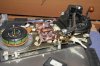
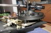
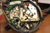
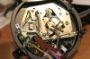
So, here we start with the disassembly. I start where the disassembly instructions I posted yesterday end.

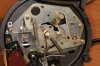
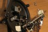
There are three Philips screws holding the tonearm assembly to the sub chasis. When the screws are undone, the tonearm is simply lifted from the chasis.
 

Attachments

  • IMG_38121.JPG
    IMG_38121.JPG
    104.3 KB · Views: 775
  • IMG_38123.jpg
    IMG_38123.jpg
    67.8 KB · Views: 651
  • IMG_38132.jpg
    IMG_38132.jpg
    85.8 KB · Views: 615
  • IMG_38133.jpg
    IMG_38133.jpg
    114.9 KB · Views: 734
  • IMG_38134.jpg
    IMG_38134.jpg
    106.8 KB · Views: 729
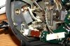
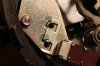
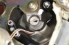
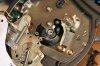
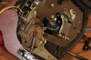
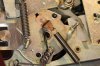
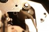
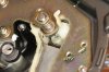
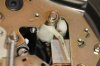
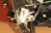
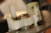
The closeup before further disassembly shows the broken offending part. In hindsight - after total stripdown - I see it is broken not where my original diagram showed but on the opposite part of the ring shaped part.

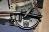
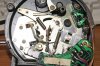
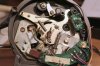
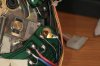
The first thing that needs to be removed is the tonearm termination PCB. It is secured by a 2 screw holder at one end and one screw through the ground wire at the other end.
 

Attachments

  • IMG_38137.jpg
    IMG_38137.jpg
    64.1 KB · Views: 669
  • IMG_38140.jpg
    IMG_38140.jpg
    83.7 KB · Views: 684
  • IMG_38143.jpg
    IMG_38143.jpg
    65.5 KB · Views: 598
  • IMG_38141.jpg
    IMG_38141.jpg
    76.8 KB · Views: 590
Next step is to undo the screw holding the spring shaped tonearm cable guide.

Then the tonearm fixing plate (TA-25) needs to be unfastened by means of the two screws securing it to the main tonearm assembly.
 

Attachments

  • IMG_38146.jpg
    IMG_38146.jpg
    87.1 KB · Views: 553
  • IMG_38144.jpg
    IMG_38144.jpg
    76.5 KB · Views: 520
In the next few pictures we see the tonearm fixing plate unfastened and shifted out of place. A bit of care needs to be excercised so as not to harm the tonearm cables. They are not as fragile as they may seem.
 

Attachments

  • IMG_38152.jpg
    IMG_38152.jpg
    62.7 KB · Views: 569
  • IMG_38150.jpg
    IMG_38150.jpg
    79.8 KB · Views: 509
  • IMG_38149.jpg
    IMG_38149.jpg
    77.3 KB · Views: 478
  • IMG_38148.jpg
    IMG_38148.jpg
    95.3 KB · Views: 530
  • IMG_38147.jpg
    IMG_38147.jpg
    94.2 KB · Views: 519
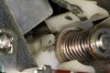
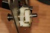
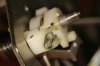
The next few pics show the riser assembly mounted in place. It comprises of two plastic parts mounted through a rod - the riser rod - which in turn is spring loaded to facilitate the lowering of the tonearm.

In other words, the plastic part that breaks is pushed by the other part that takes motion from the lever or a pin beneath that - from the automatic start/stop mechanism. They push the rod upwards to raise the tonearm. When their pressure is removed, the spring returns the tonearm down.

Damping is achieved by a snug fit of the metal rod through the shaft on the tonearm assembly and the help of some thick oil. Apart from fixing the plastic broken part, that oil seems to have dried out a bit - practically turned into goo.

Right now, however difficult it might prove to fix the plastic lever, the real challenge will be to put everything back together in a way that they work. But comparing the assembly with the tonearm blow out diagram helps and makes things seem much simpler now.
 

Attachments

  • IMG_38154.jpg
    IMG_38154.jpg
    54.6 KB · Views: 533
  • IMG_38153.jpg
    IMG_38153.jpg
    65.6 KB · Views: 532
  • IMG_38155.jpg
    IMG_38155.jpg
    56.4 KB · Views: 502
  • IMG_38156.jpg
    IMG_38156.jpg
    55.9 KB · Views: 509
  • IMG_38158.jpg
    IMG_38158.jpg
    45.5 KB · Views: 518
  • IMG_38163.jpg
    IMG_38163.jpg
    34.9 KB · Views: 539
  • IMG_38161.jpg
    IMG_38161.jpg
    44.4 KB · Views: 497
  • IMG_38160.jpg
    IMG_38160.jpg
    37.9 KB · Views: 520
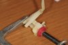
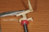
Next step is to remove the plastic levers from the riser rod. There is a C clip, a washer and a spring, then there is the broken part, another washer - which incidentally I found laying inside the tonearm base cavity - and then the top plastic part.

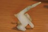
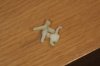
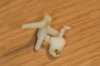
The next few pictures depict the broken part from various angles as it was removed from the "pit".

In the last two pictures I tried to depict a side that has grown worn by some sort of friction. My guess is that it happened as the plastic lever broke and the arm lift lever and assosiated metal plate shaved pieces of the plastic that could not move as designed.

I have no idea if this wear will have any mechanical effect on the operation of the piece if I am able to glue it back together and try to make it work in place.
 

Attachments

  • IMG_38164.jpg
    IMG_38164.jpg
    35.6 KB · Views: 479
  • IMG_38166.jpg
    IMG_38166.jpg
    24 KB · Views: 378
  • IMG_38167.jpg
    IMG_38167.jpg
    30.1 KB · Views: 426
  • IMG_38168.jpg
    IMG_38168.jpg
    27 KB · Views: 449
  • IMG_38169.jpg
    IMG_38169.jpg
    22.4 KB · Views: 422
  • IMG_38170.jpg
    IMG_38170.jpg
    29.4 KB · Views: 355
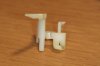
And in the next few pics I show the same assembly part after cleaning it with water and dish soap using a smooth brush. During cleaning, that small half broken piece of the ring was almost trying to go away...

What appears to be oil in these pics is actually water left over from cleaning. I didn't take any further chance with it in fear of further disintegration.

My aim is to glue the piece together, at least for the purpose of having a whole piece as reference to what is needed - perhaps custom built.
 

Attachments

  • IMG_38175.jpg
    IMG_38175.jpg
    28.1 KB · Views: 320
  • IMG_38174.jpg
    IMG_38174.jpg
    26.4 KB · Views: 326
  • IMG_38173.jpg
    IMG_38173.jpg
    45.4 KB · Views: 254
  • IMG_38172.jpg
    IMG_38172.jpg
    43.9 KB · Views: 296
  • IMG_38171.jpg
    IMG_38171.jpg
    29.6 KB · Views: 321
  • IMG_38176.jpg
    IMG_38176.jpg
    32.5 KB · Views: 340
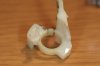
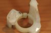
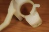
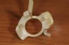
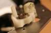
And the final pictures for now: The cleaned part clamped with glue.

I affixed two drops of cyanoacrylate glue and pressed the two edges of the broken ring together. A few minutes later I clamped it with the mini clamp as seen in the picture.

I subsequently dropped a few more drops of glue over the half-set one and used cotton buds to wipe any leaking glue.

The glue holds the pieces together, however I doubt it will be able to withstand the pressure from the raise lever. Please have a look at the second picture on post #26 to see how the raise lever applies pressure there through a metal plate.

And now I am open for suggestions. I won't do anything more tonight - it's now past midnight.
 

Attachments

  • IMG_38180.jpg
    IMG_38180.jpg
    23.8 KB · Views: 426
  • IMG_38179.jpg
    IMG_38179.jpg
    34.5 KB · Views: 420
  • IMG_38178.jpg
    IMG_38178.jpg
    38.5 KB · Views: 371
  • IMG_38177.jpg
    IMG_38177.jpg
    40.1 KB · Views: 435
You could be right. I am guessing that aluminium would be strong enough. But there are a few other plastic parts in touch with this one that might fail in case this one can take the punishment. Moreover, the piece *might* need to be elastic in order to work properly. Would Teflon be a good material?

I don't know if this is the case until I disassemble the toneram. More about that in a few hours.

Maybe something like Carbon Fiber.
 
So, here we start with the disassembly. I start where the disassembly instructions I posted yesterday end.

There are three Philips screws holding the tonearm assembly to the sub chasis. When the screws are undone, the tonearm is simply lifted from the chasis.

From the look of these pictures, if the 1500MKII is like this, i bet a 1800MKII arm would drop rite in, an fit nicely. The base looks so much like an 1800MKII as well as the 1600 and 1700MKII but those wouldn't work do to being automated arms. and you'd need the little board that controls the auto functions. But i bet an 1800MKII arm would work. Problem is finding an 1800MKII that isn't working. Trust me those are few and far between.
 
Very good work. I really appreciate the time you invested to take such detailed photographs.

Here's a quote from near the bottom of the blog linked earlier in this thread:

The plastic part refered to is way too thin where a metal shaft runs trough it. It can be repaired with glue and special thin fishing line wrapped around for reinforcement. Without the line it’s likey to break again sooner or later.
 
I've seen washers and spacers supposedly made out of teflon. It looks ... just like the material the broken part is made of.

I have studied the mechanism for lifting the arm. I need to understand how it should work or should have worked as the broken piece may have caused misalignment of levers inside the assembly.

My guess is that the failure is caused by the damping oil turning into goo and causing too much friction.

For this one, I've taken the road of glueing the riser assembly on the bearing it rotates, using that as a steel support for holding the plastic piece together.

But I need to clean everything from what is left of the damping fluid, ensure the riser assembly moves freely up and down and then apply damping.

For my first attempts - operate the tonearms cue lever, I don't need any damping so the process is focused in cleaning, testing and a clean assembly.
 

Attachments

  • IMG_38228.jpg
    IMG_38228.jpg
    35.7 KB · Views: 482
  • IMG_38229.jpg
    IMG_38229.jpg
    55.4 KB · Views: 413
  • IMG_38230.jpg
    IMG_38230.jpg
    37.8 KB · Views: 448
I've seen washers and spacers supposedly made out of teflon. It looks ... just like the material the broken part is made of.

Interesting. I'm assuming the original part (just a guess) is made out of delrin.

Your effort so far regarding this is quite impressive!:thmbsp:
 
these are realy great tt if anybody got a solution to the broken part i would be even more happy with my sl-1310 mk 2 .joel of the tt factory new how to fix it
 
The tonearm assembly is now reassembled and functional. However with several side issues:
The riser rod seems to have issues travelling vertically. Too much friction. I've cleaned the rod but not the shaft. The spring that loads the rod for lowering isn't strong enough.

The cue lever raises the rod but not smoothly. Again due to friction.

It seems that there is no other alternative than a total stripdown for thorough cleaning. I wanted to avoid unsoldering the tonearm wires but it seems there is no avoiding it.
 
LESSON LEARNT: When you are careless you make mistakes and pay the price.

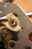
When I applied the drops of glue, I didn't realize that the rotating steel bearing was secured with a C clip of sorts. The result was that lots of glue contaminated the rotating surface making rotation difficult.

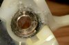
Attached is a picture of the bearing with glue. Please don't bash me. Be kind. I'm still learning...:tears:

But all is not lost. Lots of careful cleaning accompanied with closeups of the surface has already shown marked improvement. More to follow later.

It is important to point out that the broken piece problem is apparently fixed and I am now working towards solving new issues I created myself.
 

Attachments

  • IMG_38244s.jpg
    IMG_38244s.jpg
    49.7 KB · Views: 551
Last edited:
Is it possible to wrap something around the area that broke to keep it secure and re-enforce it fishing line or a small tie wrap? I am only asking because it may break again.
 
Is it possible to wrap something around the area that broke to keep it secure and re-enforce it fishing line or a small tie wrap? I am only asking because it may break again.

What you say is right. But the first problem is to find out what caused the break in the first place. After several clean/assemble/try/investigate attempts, I think I now understand the reason for failure. It is not the plastic part by itself. On the unit I'm working on I've found two reasons for the failure.

I've decided to permanently attach the plastic part to the metal pulley it is normally attached by friction. I made the mistake to glue it in place - I should have removed the pulley and glue them out of the rod, but after some tedious cleaning it is now back to normal.

I am going to present the assembly process with detailed pics and annotations to show where the problem is.
 
Back
Top Bottom