

You are using an out of date browser. It may not display this or other websites correctly.
You should upgrade or use an alternative browser.
You should upgrade or use an alternative browser.
My new Technics SL-1310MkII and the famous cueing problem
- Thread starter SaSi
- Start date


interalian
Super Member
What you say is right. But the first problem is to find out what caused the break in the first place...
In my experience with plastic parts press-fitted to metal shafts, the problem is usually expansion/contraction of the plastic part. When the part is new and is pressed onto the shaft there's a high normal force exerted which clamps it effectively to the shaft. Over time, that force becomes concentrated at a weak point in the plastic which will fracture. Your pictures seem to show the breakage at the thinnest part of the plastic piece. This is especially a problem with nylon (dimensionally unstable when exposed to varying levels of ambient moisture/humidity), the part grows and shrinks and eventually cracks.
You could drill tiny holes in the thick parts around the area that fits the shaft, thread a thin piece of wire through and twist it snug. Then you would likely have a permanent repair. If drilling isn't feasible, you could try putting the wire around the outside diameter, twist it snug, then using a soldering iron, heat the wire so it embeds slightly into the plastic, then re-tension the wire. If you use copper wire, solder the twisted part so it stays taut. These suggestions assume you have room around the part to allow for the wire.
Good luck with your repair.

Stanton681EEES
Addicted Member
In my experience with plastic parts press-fitted to metal shafts, the problem is usually expansion/contraction of the plastic part. When the part is new and is pressed onto the shaft there's a high normal force exerted which clamps it effectively to the shaft. Over time, that force becomes concentrated at a weak point in the plastic which will fracture. Your pictures seem to show the breakage at the thinnest part of the plastic piece. This is especially a problem with nylon (dimensionally unstable when exposed to varying levels of ambient moisture/humidity), the part grows and shrinks and eventually cracks.
You could drill tiny holes in the thick parts around the area that fits the shaft, thread a thin piece of wire through and twist it snug. Then you would likely have a permanent repair. If drilling isn't feasible, you could try putting the wire around the outside diameter, twist it snug, then using a soldering iron, heat the wire so it embeds slightly into the plastic, then re-tension the wire. If you use copper wire, solder the twisted part so it stays taut. These suggestions assume you have room around the part to allow for the wire.
Good luck with your repair.
Your explanation is pretty much what Joel Turner said about that part. Plus the part they designed to replace it did the very same thing.

SaSi
Seriously Illogical
You are probably right on. When I tried to fit the reglued part on the shaft, it didn't fit by a distance.In my experience with plastic parts press-fitted to metal shafts, the problem is usually expansion/contraction of the plastic part. When the part is new and is pressed onto the shaft there's a high normal force exerted which clamps it effectively to the shaft. Over time, that force becomes concentrated at a weak point in the plastic which will fracture. Your pictures seem to show the breakage at the thinnest part of the plastic piece. This is especially a problem with nylon (dimensionally unstable when exposed to varying levels of ambient moisture/humidity), the part grows and shrinks and eventually cracks.
The thinnest part of that ring - apart from obviously being the weakest point, is the point where a metal plate pushes to that ring transfering the up/down movement of the cue lever.
SaSi
Seriously Illogical
Your explanation is pretty much what Joel Turner said about that part. Plus the part they designed to replace it did the very same thing.
Based on the schematic drawing in the service manual and the actual item I see in the tonearm, the unit I have here is probably a late issue with the replacement part. Or it was repaired at some date - which isn't very likely as the cables and cable ties inside the TT were all intact and extremely well laid out.
SaSi
Seriously Illogical
Detailed assembly (or disassembly in reverse)
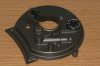
We start with the tonearm base. The attached pics show the base from the top and below.
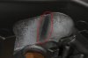
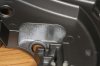
The second picture shows a friction surface that I had to polish a bit. This surface is used by the upper part of the riser assembly. As the bottom part rotates, the angled slot forces the upper part to move up and down as it is confined in that pit.
The polished surface is confining the upper part during raising of the tonearm. The opposite side during lowering.
Raising the tonearm is opposed by gravity, internal mechanism friction, the spring loading to the raiser mechanism ... and that surface. Lowering the tonearm is forced by gravity, the spring and opposed by friction in the mechanism, the opposite wall of the pit and whatever damping (fluid) is there.
I decided to leave the oposite wall untouched.
We start with the tonearm base. The attached pics show the base from the top and below.
The second picture shows a friction surface that I had to polish a bit. This surface is used by the upper part of the riser assembly. As the bottom part rotates, the angled slot forces the upper part to move up and down as it is confined in that pit.
The polished surface is confining the upper part during raising of the tonearm. The opposite side during lowering.
Raising the tonearm is opposed by gravity, internal mechanism friction, the spring loading to the raiser mechanism ... and that surface. Lowering the tonearm is forced by gravity, the spring and opposed by friction in the mechanism, the opposite wall of the pit and whatever damping (fluid) is there.
I decided to leave the oposite wall untouched.
Attachments
SaSi
Seriously Illogical
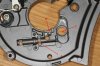
Please take a look at the first picture.
The trench marked "A" is the slot for the cue lever cylinder. It has a flap at one end - the one close to "B". "B" is the pole where the "flag" goes. The flag is pushed by the flap on the cylinder, conveying the push to the riser assembly that is positioned through the pit and hole marked as "C".
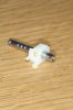
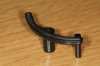
Note on the close up pic of the cylinder that the edge where the steel lever fits is broken. There is no way to fit the lever there without widening the fault. I decided to leave it as is. I can always repair that if it finaly breaks off.
That "flag" like piece also resembling a clip is - IMHO - the cause of all the troubles.
First, it is soft to allow it to act as a safety between the cue lever and the riser assembly. If - for example - the riser is stuck, the clip-looking-flag will close reducing the danger of anything breaking. A noble thought but apparently not very well executed.
A second issue I have with it is that it won't stay in it's place - over the rod marked "B". When the tonearm is in place, the rod is upside down and that means that the flag clip is hanging from the pole without any real way of being secured in place. As soon as I assembled the assembly and did some "cueing", that clip started slipping and eventlually fell off.
A third issue - with this clip again - is that while the internal assembly moves up and down by the VTA adjustment slider, that clip-flag is fixed on the tonearm base. This results in it having to push different places on the riser assembly. A few years of operation at the same VTA setting causes some wear on the plastic riser part. Combine that with a change in the VTA setting and the flag-clip starts pushing against a deformed surface. That results in further bending of the clip, reduced cueing effectiveness and eventually problems.
All the above are theories I've devised by looking at it. I haven't yet solved the problems assosiated with that clip.
And finaly, the long lever extension on the bottom part of the riser assembly is engages by a pin in the automation mechanism below to lift and lower the tonearm during start and stop. That mechanism has nothing to do with this clip and in my dry tests (mounted the tonarm and engaged the automation gear manualy) the lift worked like a charm - although undampened.
The trench marked "A" is the slot for the cue lever cylinder. It has a flap at one end - the one close to "B". "B" is the pole where the "flag" goes. The flag is pushed by the flap on the cylinder, conveying the push to the riser assembly that is positioned through the pit and hole marked as "C".
Note on the close up pic of the cylinder that the edge where the steel lever fits is broken. There is no way to fit the lever there without widening the fault. I decided to leave it as is. I can always repair that if it finaly breaks off.
That "flag" like piece also resembling a clip is - IMHO - the cause of all the troubles.
First, it is soft to allow it to act as a safety between the cue lever and the riser assembly. If - for example - the riser is stuck, the clip-looking-flag will close reducing the danger of anything breaking. A noble thought but apparently not very well executed.
A second issue I have with it is that it won't stay in it's place - over the rod marked "B". When the tonearm is in place, the rod is upside down and that means that the flag clip is hanging from the pole without any real way of being secured in place. As soon as I assembled the assembly and did some "cueing", that clip started slipping and eventlually fell off.
A third issue - with this clip again - is that while the internal assembly moves up and down by the VTA adjustment slider, that clip-flag is fixed on the tonearm base. This results in it having to push different places on the riser assembly. A few years of operation at the same VTA setting causes some wear on the plastic riser part. Combine that with a change in the VTA setting and the flag-clip starts pushing against a deformed surface. That results in further bending of the clip, reduced cueing effectiveness and eventually problems.
All the above are theories I've devised by looking at it. I haven't yet solved the problems assosiated with that clip.
And finaly, the long lever extension on the bottom part of the riser assembly is engages by a pin in the automation mechanism below to lift and lower the tonearm during start and stop. That mechanism has nothing to do with this clip and in my dry tests (mounted the tonarm and engaged the automation gear manualy) the lift worked like a charm - although undampened.
Attachments
-
 IMG_38268.jpg44.5 KB · Views: 397
 -
 IMG_38267.jpg52.9 KB · Views: 387
 -
 IMG_38266.jpg49.7 KB · Views: 395
 -
 IMG_38264.jpg53.6 KB · Views: 448
 -
 IMG_38262.jpg87.2 KB · Views: 417
 -
 IMG_38275.jpg40.7 KB · Views: 326
 -
 IMG_38272.jpg27.5 KB · Views: 318
 -
 IMG_38271.jpg27 KB · Views: 338
 -
 IMG_38270.jpg33.9 KB · Views: 360
 -
 IMG_38269.jpg46.6 KB · Views: 355
SaSi
Seriously Illogical
Don't rush things
This posting and picture is dedicated to my stupidity. Here, I've said it, so you don't have to do it for me
If you look at a previous post, the brass bearing on which the plastic riser part is fixed, is filled with drops and spills of glue. That glue didn't allow a free rotation.
I summized my model working skills and tried to clean those spills as best as I could, not really believing it would work. But with lots and lots of patience, I managed to clean that piece from excess glue, uncovered the clip that secures the bearing on the shaft and gave enough clearance to the bearing to rotate freely.
I believe it now rotates as it should and is as good as new in that respect. We do still have an issue with some missing plastic that was broken and chopped away by the clip-flag over the years. That may or may not be important but is part of the clip-flag problem and syndrome.
So, I will finish this post by restating: If you do anything like this, don't rush things, think twice, take close up pics if you can and study them before deciding how to proceed.
This posting and picture is dedicated to my stupidity. Here, I've said it, so you don't have to do it for me
If you look at a previous post, the brass bearing on which the plastic riser part is fixed, is filled with drops and spills of glue. That glue didn't allow a free rotation.
I summized my model working skills and tried to clean those spills as best as I could, not really believing it would work. But with lots and lots of patience, I managed to clean that piece from excess glue, uncovered the clip that secures the bearing on the shaft and gave enough clearance to the bearing to rotate freely.
I believe it now rotates as it should and is as good as new in that respect. We do still have an issue with some missing plastic that was broken and chopped away by the clip-flag over the years. That may or may not be important but is part of the clip-flag problem and syndrome.
So, I will finish this post by restating: If you do anything like this, don't rush things, think twice, take close up pics if you can and study them before deciding how to proceed.
Attachments

SaSi
Seriously Illogical
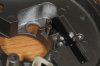
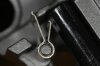
The cue lever and flag-clip in action
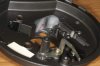
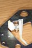
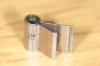
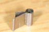
The next few pics show the cue lever's cylinder with flap interacting with the flag-clip. As seen, the clip's short end is pushed by the clue flap and turns the clip, making the long face of the clip push and rotate the riser assembly's base part.
That flag-clip has nicely formed edges that are supposed to ensure a firm nice contact between the clip and the riser assembly.
Also note that offset cut guide by the pole ensuring the clip doesn't rotate past the allowed range. Once the long edge reaches that fence it stops there. The short edge, if further pushed by the cue flap, can still go a bit further closing the clip and relieving pressure from the cue lever.
One of the issues is that the flag-clip reaching the edge of the fence, hasn't pushed the riser assembly all the way of it's travel to ensure max elevation. Can be an issue caused by the break of the piece? I really can't tell.
The next few pics show the cue lever's cylinder with flap interacting with the flag-clip. As seen, the clip's short end is pushed by the clue flap and turns the clip, making the long face of the clip push and rotate the riser assembly's base part.
That flag-clip has nicely formed edges that are supposed to ensure a firm nice contact between the clip and the riser assembly.
Also note that offset cut guide by the pole ensuring the clip doesn't rotate past the allowed range. Once the long edge reaches that fence it stops there. The short edge, if further pushed by the cue flap, can still go a bit further closing the clip and relieving pressure from the cue lever.
One of the issues is that the flag-clip reaching the edge of the fence, hasn't pushed the riser assembly all the way of it's travel to ensure max elevation. Can be an issue caused by the break of the piece? I really can't tell.
Attachments



SaSi
Seriously Illogical
Time to revive this before it gets forgotten. I have to go on with the assembly process that was interrupted by the post-carnival festivities here in Athens and my family obligations.
I have to say - can't wait - that the TT is already assembled and succesfully did the "dry run" test. The run was virtually dry as the dampening fluid that was partly gone is now thoroughly cleaned from the assembly.
I just placed the assembled tonearm on it's place - didn't fasten it - and then placed the top plinth cover with electronics over the unit, connected the plugs and fired it up.
The mechanism pins and rods engaged correctly and the tonearm is well lifted by the automation levers to be transported on and off the LP. And as the automation rods remove the pressure from the riser mechanism gradually, the lack of damping fluid isn't really visible during the start operation.
But I feel I still need to perfect the manual lift/lowering of the tonearm and ensure that the cue clip will remain in place after several days and months and years.
The cue lever is a weaker as described in a previous post, due to the clip-flag.
I have to say - can't wait - that the TT is already assembled and succesfully did the "dry run" test. The run was virtually dry as the dampening fluid that was partly gone is now thoroughly cleaned from the assembly.
I just placed the assembled tonearm on it's place - didn't fasten it - and then placed the top plinth cover with electronics over the unit, connected the plugs and fired it up.
The mechanism pins and rods engaged correctly and the tonearm is well lifted by the automation levers to be transported on and off the LP. And as the automation rods remove the pressure from the riser mechanism gradually, the lack of damping fluid isn't really visible during the start operation.
But I feel I still need to perfect the manual lift/lowering of the tonearm and ensure that the cue clip will remain in place after several days and months and years.
The cue lever is a weaker as described in a previous post, due to the clip-flag.


SaSi
Seriously Illogical
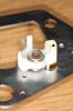
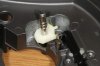
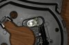
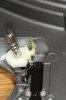
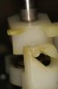
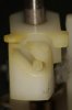
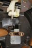
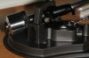
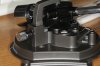
In the next few pics you can see the details of the riser assembly working as a system. The lower part of that is rotated as pushed by the clip. The upper part of the riser is governed by the angled slot converting the rotation of the lower part into a rise.
Attachments
SaSi
Seriously Illogical
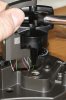
Before mounting the riser assembly, we need to remount the tonearm wand and bearings to the base.
The tonearm is simply dropped in place from above. The VTA fastening bolt is what keeps it there for start.
The tonearm is simply dropped in place from above. The VTA fastening bolt is what keeps it there for start.
Attachments
Last edited:
SaSi
Seriously Illogical
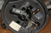
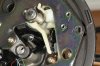
Then the riser assembly mounted on the tonearm "base plate" is put in place. It is secured in place with two screws seen in pic 2 as well as the arm rest rod using a hex nut.
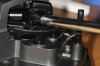
Finally, the arm riser is mounted from the top. It needs to be pressed down as the slotted / hex screw is tightened in place.
I may be wrong as the tonearm is currently running dry and less than idealy in terms of lift, but it seems that the rise depends on the VTA. For lower VTA values (lower tonearm levels) the riser adjustment needs to be undone.
Finally, the arm riser is mounted from the top. It needs to be pressed down as the slotted / hex screw is tightened in place.
I may be wrong as the tonearm is currently running dry and less than idealy in terms of lift, but it seems that the rise depends on the VTA. For lower VTA values (lower tonearm levels) the riser adjustment needs to be undone.
Attachments



SaSi, Thank you for all the pics and the step by step How To. I just picked up a working SL-1900 for $2.50 with this very same cuing return issue. When I'm feeling good and confident, I will venture into the interior of this table and see what I can do.

SaSi
Seriously Illogical
Thank you all for your kind words. I was initially intimitaded by the blow up diagram of the tonearm but eventually it ended up being much simpler to handle compared to a tape deck or a cassette deck.
I worked the TT last night with everything just clipped together - no screws. I set it to auto repeat - the countdown works fine - and luckily the stylus guard of the OM5 cart that came with it glides nice and smoothly over the mat to the center of the platter (when no antiscating is applied). I left the unit auto playing the matt for an hour or so. Each cycle lasts about 20 secs including lift and move out - in, so I guess it repeated the process between 150 and 200 times.
I was expecting the clip to fall off. It should but it didn't.
I also received a nice jar of Technics cassette door damping fluid. It's more like molassa and I guess it will do just fine for damping the tonearm.
Still need to find a way to improve the manual lift travel, although it is functionally ok as it is. The automation lifts the tonearm about an inch from the mat while the manual lever lifts it about 1/4 of an inch.
I worked the TT last night with everything just clipped together - no screws. I set it to auto repeat - the countdown works fine - and luckily the stylus guard of the OM5 cart that came with it glides nice and smoothly over the mat to the center of the platter (when no antiscating is applied). I left the unit auto playing the matt for an hour or so. Each cycle lasts about 20 secs including lift and move out - in, so I guess it repeated the process between 150 and 200 times.
I was expecting the clip to fall off. It should but it didn't.
I also received a nice jar of Technics cassette door damping fluid. It's more like molassa and I guess it will do just fine for damping the tonearm.
Still need to find a way to improve the manual lift travel, although it is functionally ok as it is. The automation lifts the tonearm about an inch from the mat while the manual lever lifts it about 1/4 of an inch.
Stanton681EEES
Addicted Member
Your problem with the cuing is something completely different. The problem with his table and the two other tables from that series 1400 and 1500MKII was a badly designed part.SaSi, Thank you for all the pics and the step by step How To. I just picked up a working SL-1900 for $2.50 with this very same cuing return issue. When I'm feeling good and confident, I will venture into the interior of this table and see what I can do.
SaSi
Seriously Illogical
The unit is completely assembled and working. First time I heard an LP through it.
I used a Technics cassette lid dampener fluid (RZZ0L08) and "drowned" the riser assembly and spring in it. The riser now works nicely - the automation lifter works slightly better. I am going to use the same fluid in the 1500 manual one that shows lacking damping on the riser.
I know I could have fixed it a bit better and I will probably try that if a decent shaped MkII comes along in a fair price.
I will work on the same TT in some time. For the time being I am waiting to see if the contraption I've devised to keep that POS clip in place holds. It should - I'm hoping - but I can't be sure.
I am not terribly impressed with the TT though. In the looks department it's a killer but in terms of dampening from the floating chasis I am not certain that the effect is all that good. I think I like the SL-1210MkII better - way better. And the VTA adjustment on the 1210 is the real thing, making the 1310MkII appear as a toy in that respect.
I've taken some more detailed pictures of the assembly and lubrication. I will post them tomorow as it is a bit late here now.
I used a Technics cassette lid dampener fluid (RZZ0L08) and "drowned" the riser assembly and spring in it. The riser now works nicely - the automation lifter works slightly better. I am going to use the same fluid in the 1500 manual one that shows lacking damping on the riser.
I know I could have fixed it a bit better and I will probably try that if a decent shaped MkII comes along in a fair price.
I will work on the same TT in some time. For the time being I am waiting to see if the contraption I've devised to keep that POS clip in place holds. It should - I'm hoping - but I can't be sure.
I am not terribly impressed with the TT though. In the looks department it's a killer but in terms of dampening from the floating chasis I am not certain that the effect is all that good. I think I like the SL-1210MkII better - way better. And the VTA adjustment on the 1210 is the real thing, making the 1310MkII appear as a toy in that respect.
I've taken some more detailed pictures of the assembly and lubrication. I will post them tomorow as it is a bit late here now.