• The move to the new server is done. There are some software and database maintenance updates in process. This has us passing the hat around to help out. We appreciate any donations. Seriously, even a dollar helps. The payment page may be found here - https://www.audiokarma.org/support.html

My SA - 7100 Drops in and out of Protection

I've checked the board numbers and they all correspond to the schematic numbers.
There is, however, an additional "letter" on the end of each.
Here they are as follows.
AWH-021 A
AWF-005 B
AWG-016 B
AWM-027 D
AWR-026 B

What does the extra letter denote ?
These letters do not appear on the schematic, only the preceding.

I'm now working on the protection board as we speak.
Will post back updated board later.
Thanks
 
I'm just on the protection board and just noticed I don't have a part number for C1 and C2. These weren't on the list originally compiled.

On my board these are 0.22/10.
As I don't have these specific items on hand, what would make a good substitute?

I have some spare 2.2 50 647-UKL1H2R2MDDANA. Will these work ?

I did notice that on the schematic list, it shows both C1 and C2 as being Mylar 0.056 50v (p/n CQMA563K 50).

Can one use electrolytic caps in place of Mylar ? What's the difference ? Is 50v too high ?

Also Q1 and Q2 appear as 2SC869 on the schematic, but the parts list lists these as 2SC857.

Qu. Can I still use the 512-KSC1845FTA ?
 
Last edited:
The original C1 and C2 caps should be electrolytic (small blue Sanyo, usually). Their value is critical to the proper functioning of the protection circuit. I replace these caps with small stacked film caps.

Transistors are fine.
 
I used Panny ECW (because I had some) or you could use ECQ .22uf for C1 and C2.

I also had 2SC869 and did use 1845's just check the pin outs for proper install.


I'm just on the protection board and just noticed I don't have a part number for C1 and C2. These weren't on the list originally compiled.

On my board these are 0.22/10.
As I don't have these specific items on hand, what would make a good substitute?

I have some spare 2.2 50 647-UKL1H2R2MDDANA. Will these work ?

I did notice that on the schematic list, it shows both C1 and C2 as being Mylar 0.056 50v (p/n CQMA563K 50).

Can one use electrolytic caps in place of Mylar ? What's the difference ? Is 50v too high ?

Also Q1 and Q2 appear as 2SC869 on the schematic, but the parts list lists these as 2SC857.

Qu. Can I still use the 512-KSC1845FTA ?
 
The original C1 and C2 caps should be electrolytic (small blue Sanyo, usually). Their value is critical to the proper functioning of the protection circuit. I replace these caps with small stacked film caps.

Transistors are fine.

Thanks EW, I was concerned about these because, clearly, on my board they are the blue Sanyo electrolytics. The information provided by the schematics calls for mylar, and a different value.
Sorry for this noob question. When you say film caps do you mean mylar ?
Can you provide a part number for the recommended item so I can order the correct part please ?
Much appreciated :thmbsp:
 
I used Panny ECW (because I had some) or you could use ECQ .22uf for C1 and C2.

I also had 2SC869 and did use 1845's just check the pin outs for proper install.

I actually pulled out an 1845 with the view to install it and did the orientation check. But prior to diving in, I chimed in for reassurance.
Thanks for confirming this for me. One less thing I need to worry about now.
Cheers mate !
 
Protection Board. AWM-027

Its been a while and I finally found some time.
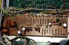
Protection board now completed. Diodes replaced too. Feel free to scrutinize these. I checked for correct orientation, but if someone can confirm this I'd appreciate it.
Please see pic.
 

Attachments

  • Protection Board IV.jpg
    Protection Board IV.jpg
    101.2 KB · Views: 51
  • IMG_2034 - Copy.jpg
    IMG_2034 - Copy.jpg
    109.7 KB · Views: 51
  • IMG_2037.jpg
    IMG_2037.jpg
    71.1 KB · Views: 46
Last edited:
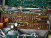
Here is a pic of my finished board to compare:
Anything marked with white dot has been replaced, I did not replace all transistors only those deemed failure prone.
The Atlas DCA55 makes life easy, pull transistor put on tester make sure silk screen on board is correct, put new transistor on DCA55 and verify pin out and install. Saves time for me, although you can just keep track with notes and check data sheet for pin outs.

From my notes:

Q1/Q2 are 2SC869 use 512-KSC1845FTA
Q3/Q4 are 2SC945 use 512-KSC2383YTA
Q5 are 2SC733 use 512-KSA992FBU (you may want to double check this one)
Q6 are 2SC945 all the way to the right below Q7 same as above
Q7 are 2SC1384 use 512-KSC2690AYS


Last edited:
Protection Board. AWM-027

Here is a pic of my finished board to compare:
Anything marked with white dot has been replaced, I did not replace all transistors only those deemed failure prone.
The Atlas DCA55 makes life easy, pull transistor put on tester make sure silk screen on board is correct, put new transistor on DCA55 and verify pin out and install. Saves time for me, although you can just keep track with notes and check data sheet for pin outs.

From my notes:

Q1/Q2 are 2SC869 use 512-KSC1845FTA
Q3/Q4 are 2SC945 use 512-KSC2383YTA
Q5 are 2SC733 use 512-KSA992FBU (you may want to double check this one)
Q6 are 2SC945 all the way to the right below Q7 same as above
Q7 are 2SC1384 use 512-KSC2690AYS


Thanks for the heads up Pat. I have actually been using your board pics as a Guide, but somehow I just missed replacing that Q7. I've just soldered it in.
These notes courtesy of Mark.
Q1/Q2 are 2SC869 = 512-KSC1845FTA
Q3/Q4 are 2SC945 = 512-KSC1845FTA. I also used (as per MTF's List)
Q5 is 2SA733 = 512-KSA992FBU (this too as per MTF)
Q6 is 2SC945 = 512-KSC2383YTA (Used 512-KSC1845FTA. Also as per MTF)
Q7 is 2SC1384 = 512-KSC2690AYS

One more to go !
**NOTE** First pic is of board Pre surgery.
 

Attachments

  • Protection Board IV.jpg
    Protection Board IV.jpg
    100.9 KB · Views: 30
  • Protection Board. Updated.jpg
    Protection Board. Updated.jpg
    74.1 KB · Views: 32
Power Supply AWR-026

Hi Gents,

Just completed the power supply board. :banana:

power supply
awr-026. c1 220 50 cea 220 50 647-UPW1H221MPD6
awr-026 . c2 100 50 cea 100 50 647-UPW1H101MPD
awr-026. c4 100 35 cea 100 35 647-UPW1V101MPD
awr-026. c5 220 35 cea 220 35 647-UPW1V221MPD
awr-026. c10 220 50 cea 220 50 647-UPW1H221MPD6
awr-026. c11 220 50 cea 220 50 647-UPW1H221MPD6
awr-026. q1 2sd313 512-KSC2073TU
awr-026. q2 2sc945 512-KSC2383YTA
awr-026. d1 sib01-02 400 1a 512-1n4004
awr-026. d2 sib01-02 400 1a 512-1n4004
awr-026. d3 wz-130 13v zener 500mW 512-1N5243B
awr-026. d4 ds-118 400 3a 400 3a 512-1N5404
awr-026. d5 ds-118 400 3a 400 3a 512-1N5404
awr-026. d6 ds-118 400 3a 400 3a 512-1N5404
awr-026. d7 ds-118 400 3a 400 3a 512-1N5404

All comments welcome.
Pics as follows.
 

Attachments

  • IMG_2069.jpg
    IMG_2069.jpg
    55.7 KB · Views: 36
  • IMG_2067.jpg
    IMG_2067.jpg
    100.7 KB · Views: 41
  • IMG_2060.jpg
    IMG_2060.jpg
    76.6 KB · Views: 31
  • IMG_2049.jpg
    IMG_2049.jpg
    36.3 KB · Views: 32
  • IMG_001.Power Supply.jpg
    IMG_001.Power Supply.jpg
    106.7 KB · Views: 38
Thanks Pat. Just the Power Amp (AWH-021) to go before I start doing cart wheels.
I'll report back when done or during if need be.
Cheers guys !
 
Power Amp (AWH-021)

Hi gents,
I'm on a roll here..
I've just changed out everything but the trimmers and the output transistors.

Q1. Do the trimmers VR 1, VR 2(652-3296P-1-502LF), VR 3, VR 4 (652-3386H-1-101LF), need to be mounted in a specific way, pin wise ? I'm wondering this because the trim screw needs to be accessible first of all, facing away from heat sink. These are 3 pin items.
Q2. I've never replaced output transistors before. Can someone guide me on this too please. Perhaps a link with pics would be perfect.
Thanks :thmbsp:
 

Attachments

  • IMG_2071.jpg
    IMG_2071.jpg
    49.2 KB · Views: 30
  • IMG_2077.jpg
    IMG_2077.jpg
    78.5 KB · Views: 39
  • IMG_2082.jpg
    IMG_2082.jpg
    77.7 KB · Views: 32
  • IMG_2079.jpg
    IMG_2079.jpg
    38 KB · Views: 27
For the trimmers I always go by the 3386 data sheet, and choose the proper value, then match the pin out orientation of the originals, and then location of adjustment screw.

*******If you have the opposite pin out the leads on the trimmers are to short to bend the other way.

I like these also:

Have used them on many Advent 300's.

http://www.digikey.com/product-detail/en/3329S-1-202LF/3329S-202LF-ND/1060399

Check the above data sheet for part number for pin outs and style

If you need help picking out let me know if facing the heatsink are there 2 pins up front and one center rear, or a single pin up front with 2 in the back?

You are probably going to need top adjusters for the 2 center ones, or if you need the ones you have in the pic, see if you can angle them to the outside so you can adjust them, that is if the pin out are correct.
 
Last edited:
This is a nice video from ChrisMarantz of Faultline Audio showing the outputs getting ready to install.
Let me know if you need Digikey or Mouser numbers for new mica, as I do not see it in your pic.

http://www.faultlineaudio.net/videos/?currentPage=3

Thanks for going to the trouble providing the info Pat.
So the transistors are just a matter of unscrewing and they should just pop out.
Sorry for the noob questions, I just don't want to screw things up come this far.
When you say "Mica" do you mean the insulating sheets for the transistors ?
If so, you think mine can be re used ?

*Update*.
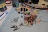
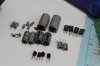
Just removed the outputs. Very simple. There seems to be no trace of thermal paste but rather, it looks like some kind of super glue residue..
 

Attachments

  • IMG_2122.jpg
    IMG_2122.jpg
    33.4 KB · Views: 22
  • IMG_2123.jpg
    IMG_2123.jpg
    54.9 KB · Views: 27
Last edited:
Back
Top Bottom