• The move to the new server is done. There are some software and database maintenance updates in process. This has us passing the hat around to help out. We appreciate any donations. Seriously, even a dollar helps. The payment page may be found here - https://www.audiokarma.org/support.html

My SA - 7100 Drops in and out of Protection

For the trimmers I always go by the 3386 data sheet, and choose the proper value, then match the pin out orientation of the originals, and then location of adjustment screw.

*******If you have the opposite pin out the leads on the trimmers are to short to bend the other way.

I like these also:

Have used them on many Advent 300's.

http://www.digikey.com/product-detail/en/3329S-1-202LF/3329S-202LF-ND/1060399

Check the above data sheet for part number for pin outs and style

If you need help picking out let me know if facing the heatsink are there 2 pins up front and one center rear, or a single pin up front with 2 in the back?

You are probably going to need top adjusters for the 2 center ones, or if you need the ones you have in the pic, see if you can angle them to the outside so you can adjust them, that is if the pin out are correct.

The trimmers I already have, These were on the list Mark put together for me. I purchased them as directed so I assume they are the right ones, ie, value etc.
I just wasn't sure on the orientation.. pin out.
 
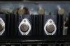
Yes looks like thin plastic sheet/insulator between heatsink and transistors. If they are in really good shape you can wipe clean and reuse, if they have any cracks or chips you can short the case to the heat sink. I usually order a bunch at a time they are cheap.


Thanks for going to the trouble providing the info Pat.
So the transistors are just a matter of unscrewing and they should just pop out.
Sorry for the noob questions, I just don't want to screw things up come this far.
When you say "Mica" do you mean the insulating sheets for the transistors ?
If so, you think mine can be re used ?
 
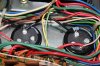
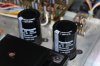
Looks like if you put them in but tweek them to the left you will be able to adjust, due to the 2 caps in front of them.


The trimmers I already have, These were on the list Mark put together for me. I purchased them as directed so I assume they are the right ones, ie, value etc.
I just wasn't sure on the orientation.. pin out.
 
Yes looks like thin plastic sheet/insulator between heatsink and transistors. If they are in really good shape you can wipe clean and reuse, if they have any cracks or chips you can short the case to the heat sink. I usually order a bunch at a time they are cheap.

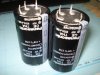
I just put in an order for those Panasonic main filter caps the other day. My supplier is interstate so I'll call them up first thing Monday and I'll just add a bunch of these to my order. Can't hurt to have some extras.
I'd rather just replace these too than use old ones.
If you can provide the mouser p/n for these I'd be grateful.
Thanks Pat :thmbsp:
 
Last edited:
Thank you muchly !

I've just sent an email to my supplier, and hopefully my initial order hasn't been processed yet and these can be added.
 
Got my Panasonic CE THA 80V 8200uF caps today. Unfortunately those mica insulators missed the order so it's likely I'll see those on Monday. Then I'll be installing the new TO3 transistors and the caps to finish of this project.
Then the threshold moment..Start up ! :music:
I'll try and put together a DBT, but will need help on where to hook it up.
 

Attachments

  • DSC05736 - Copy.JPG
    DSC05736 - Copy.JPG
    162.2 KB · Views: 28
Last edited:
Quick question Pat. I'm assuming you'd answer this question anyway.
When you replaced your outputs, were they Toshiba Items?
My old ones are Toshiba, and I was just wondering if these are the original items.
Also was your insulator of the clear plastic type ?
There was no trace left of any thermal paste, only what looked like a hardened clear substance. Does thermal paste go off this way over time ?
Thanks
 
Quick question Pat. I'm assuming you'd answer this question anyway.
When you replaced your outputs, were they Toshiba Items?
My old ones are Toshiba, and I was just wondering if these are the original items.
Also was your insulator of the clear plastic type ?
There was no trace left of any thermal paste, only what looked like a hardened clear substance. Does thermal paste go off this way over time ?
Thanks

I did not replace my outputs, if the units I get are functioning nicely and I am able to make all audio adjustments I leave them in. I do not remember if mine were Toshiba or Hitachi's. If all 4 are Toshiba's I am betting they are original. The factory Pioneer/Marantz at one time used a "clear" thermal paste so hard to tell. The thermal paste is only to fill small gaps and is used sparingly not "caked" on.

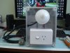
A trip to Home Depot or Lowes and approx 20.00 and you have yourself a nice DBT:

This was the easiest and best plans I have seen:

Here is mine:


Link:
http://www.audiokarma.org/forums/showthread.php?t=465423
 
Last edited:
I no longer have it and I kind of regret it though. It was a very solid and fine sounding piece of gear. I rebuilt it like I was keeping it for myself.

This was the feedback I got from the gentleman that purchased it from me:

STUNNING Pioneer SA-7100 Amplifier! Blown Away!!!!!


Thanks for your info again Pat.
Do you still have your SA-7100 ? If so or not, how would describe its performance ?
 
Question Please

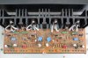
I've completed the power amp to include the TO3 transistors, new trim pots and main filter caps.

Prior to hooking up to the DBT, how should I set the trim pots ?

I realise the offset and bias need to be adjusted, but for the purposes of the DBT do these need to be set in a particular way ?
 

Attachments

  • IMG_2283.JPG
    IMG_2283.JPG
    227.8 KB · Views: 31
  • IMG_2279.JPG
    IMG_2279.JPG
    163.2 KB · Views: 24
  • IMG_2275.JPG
    IMG_2275.JPG
    212.6 KB · Views: 30
  • IMG_2273.JPG
    IMG_2273.JPG
    238 KB · Views: 26
  • IMG_2270.JPG
    IMG_2270.JPG
    159.2 KB · Views: 28
Patfont> For clarity's sake, setting bias trimmer to=max value; you mean max RESISTIVE value, correct?
 
no, max resistance would be max idle current.
MINIMUM resistance, Minimum idle current.

Set the DC offset pots to the center of their rotation. That is correct...
 
Last edited:
I did not replace my trimmers but.......

When I do replace trimmers I measure the old trimmer across an outside leg and the center wiper and set the new as close to that as I can.

or

offset trimmers=center
bias=max value

def. use dim bulb.

So you obviously measured the old and the new out of circuit. ?? If so, I wish I'd remembered to do this prior to installation.

The new pots are already in and I cannot get the values to change when winding up or down. (resistance check like you said across wiper and one leg).

The old ones measure ok and do change resistance when adjusted.

Sorry for this dumb question, but which is which ?

I have this directly from the schematic list.

Idle Current Adjustment = VR3, VR4 (30Mv)

Mid Point Potential adjustment = VR1, VR2 (under 10Mv).

I'm guessing the offsets are the 2 outer ones, but I don't like to guess.:scratch2:

Also my DBT I just put together..
 

Attachments

  • DSC05802.JPG
    DSC05802.JPG
    124.2 KB · Views: 24
  • DSC05806.JPG
    DSC05806.JPG
    126.8 KB · Views: 27
now you have me concerned that you have the correct pots themselves in the correct positions.,
 
Hi Mark. It's been a while. Hope your well.

Thanks for your info, You came in whilst I was composing my reply.

I just need to set these trimmers roughly to where they should be prior to the DBT.

So I'm assuming the offsets are the outer 2, VR3, VR4.

how should I adjust the center 2 ?

Thanks
 
now you have me concerned that you have the correct pots themselves in the correct positions.,

Why do you think that ?

I purchased the pots as per the parts list and prior to installation I checked off the part number.

awh-021 vr1 4.7k 25t 652-3296P-1-502LF
awh-021 vr2 4.7k 25t 652-3296P-1-502LF
awh-021 vr3 100 ohms 652-3386H-1-101LF
awh-021 vr4 100 ohms 652-3386H-1-101LF
 
Last edited:
I usually say zero ohms by measuring with an ohmmeter to avoid having the cw / ccw conundrum. Direction is a function of how the pc board was designed. We really can't follow that blindly, and never generalize, especially on matters of rotation direction.

On a bias diode circuit an increase in resistance in the thermal diode current path results in greater voltage across the diodes, all the way down the chain to an increase of the 0.6v or so (like to 0.8v or greater) emitter to base voltage on the output transistors.

ohm's law - assume 7 milliamps of thermal bias diode current in that circuit, current times ohms = volts, thus an additional 100 ohms yields an additional 0.7v which divided by two (+/- 0.6v for two transistors is 1.2v total, and ADD 1.2v for every stage in between the diode circuit and the outputs) is +/- 0.95V (1.2 + 0.7 = 1.9 /2 = 0.95v)
 
Last edited:
He is I believe refering to me, not you. Sorry but my notes are wrong on the initial setting for bias trimmers.


when you fix/edit your posts (PLEASE - don't want that in print - EVER - ), I will remove my objection.

With respect, but you have lost me. :dunno:

Did I do something wrong here ?

I'm just hanging to complete this project and just need to know what to do with these trimmers before I power it on the DBT as per my previous posts.
 
Back
Top Bottom