• The move to the new server is done. There are some software and database maintenance updates in process. This has us passing the hat around to help out. We appreciate any donations. Seriously, even a dollar helps. The payment page may be found here - https://www.audiokarma.org/support.html

NAD 3020A - ceramic disc cap replacement in pre amp

Hifibythekg

Super Member
Hi,

Has anybody successfully replaced the ceramic discs filters in the phono / pre amp section of this amp?

On paper this mod sounds excellent, but in practice did it bring about an improvement in sound quality?

Sourcing the right components seems like a minefield!

Consequently, would be very grateful for any recommendations and/or photos of finished mods.
 
Register to hide this ad
The topology of the 3020 phono and preamp stages were often seen in later NAD units with film capacitors instead of ceramic types, e.g., the NAD1000/106 phono stage is essentially identical to that of the 1020/3020 one.
 
Thanks, Leestereo. Just saw your thread at
https://audiokarma.org/forums/index.php?threads/nad-106-preamp-restoration-upgrade-project.550017/
... incredible job!
Having recapped the amp I'm very tempted to upgrade the ceramics.
Very much hoping that someone will have a parts list, easy-ish to follow guide.
From what I can see written on the caps..

C403........................ -24,8
C404........................ 47p
C405 and C406........56
C411 and C412........68
C509 and C510....... 221M KCK
C511 and C512.......101
C515 and C516...... L 5 (or maybe just an 'L' shaped line within which there the numeral '5')

Also one large ceramic disc with '104 EAE' written on it.
The NAD service manual's parts list doesn't match up on several caps, but I think that this is generally well accepted.
Again, would be grateful for any help on this.
 
If you post the part of the schematic that includes the ceramic capacitors you want to replace, I may be able to assist.
 
Thanks for offering. Really appreciated.
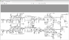
I'm not sure whether this schematic is entirely accurate..
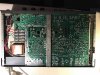
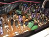
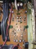
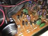
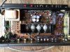
Also some pics of my board. There's one shot that shows the board with the original lavender caps and I've highlighted the 6 ceramics with pink dots.
Although please suggest any others that would help the pre and phono section.


IMG_7095 copy.jpg IMG_7145 copy.jpg IMG_7146 copy.jpg IMG_7147 copy.jpg Screenshot 2021-03-17 at 17.57.21.png

IMG_7080 copy.jpg
 
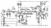
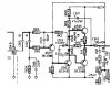
@Hifibythekg: The schematic you posted appears to be for the 3020 and doesn't match your "A" variant. I could not find a schematic specifically for the 3020A, but did find one for the 3020B which matches your unit better.

3020B phono.jpg

3020B pre.jpg

I suggest that the ceramic capacitors in the signal path, i.e., C403/C404 (47pF); C411/C412 (68pF) and C509/C510 (220pF) be replaced with C0G types. The other ceramics are Miller capacitors and need not be replaced.
 
Last edited:
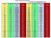
2-digit cap markings are in pF. 3-digit markings are demystified using this chart.

You will not see every possible 3-digit ceramic disc code here and just have to use the same logic to find your answer. For example, 470 = 0.047nF, or 0.000047uF, so 560 = 0.056nF, or 0.000056uF.

ceramic-capacitor-code-table-2-1024x775.jpg
 
Thank you Leestereo for going the extra mile and checking out the schematic.
Onanysunday, that's a nice piece of demystification..
I'm not sure if a 3020A version exists, I think people have to use the 3020 or the 3020B as a starting point.
I'm keen to make these modifications but still find the component search challenging even with your excellent advice so far.
The link to Farnell in the UK shows 29 options just for the 47pF !
Eternally grateful etc etc. if someone might be able to pick out the likely best choice for the pairs of:
C403 47pF
C411 68pF
C509 220pF
https://uk.farnell.com/w/c/passive-...apacitors?capacitance=47pf&range=inc-in-stock

In any event, many thanks.
 
The first 2-digits in a 3-digit code is the capacitance value, the 3rd digit tells you how many zeros to add, starting with a 3-digit code ending in "0" representing the "xx" range, or 1-99 pF.

100 = 10 pF
101 = 100 pF
102 = 1,000 pF
103 = 10,000 pF
104 = 100,000 pF
 
Thank you gentlemen.
Leestereo that's just what I needed, thank you. Looking forward to ordering and getting to a higher level!
Onanysunday thank you, sincerely. (Rereading my response it might have appeared that I was being sarcastic, I wasn't.) The table you posted is an easy to read reference and it makes navigation around these values a whole lot easier. Thank you!
 
You know, if you're feeling energetic, you could always replace the resistors with 1% metal film. How far you want to go is how much time you want to spend. Since you said you are going to use it for vinyl, you could start with the phono preamp.

Lee.
 
I am now counting 11 ceramics in the phono section, judging from your top-view photo. 5 pairs of small ones, as well as one large disc in the middle that should also be replaced. I prefer polypropylene over multi-layer COG/NP0 types, but that's just my opinion. It may be closer to the original sound to stick with the MLCC's, but both types are a definite performance improvement. Polystyrenes would be my gold-standard, but those are hard to find and easily heat damaged while soldering.
 
Thanks Leesonic, tempting, and they do look nice.
For the phono preamp how may would that be? Less than 20?
While you're there I'm challenged by the prospect of adjusting the bias and replacing those resistors with the Bourns..
Is there a picture or thread that makes this easy to understand? I have the Bourns to hand and ready to solder..
 
You know, if you're feeling energetic, you could always replace the resistors with 1% metal film. How far you want to go is how much time you want to spend. Since you said you are going to use it for vinyl, you could start with the phono preamp.

Lee.
Thanks Leesonic, tempting, and they do look nice.
For the phono preamp how may would that be? Less than 20?
While you're there I'm ridiculously challenged by the prospect of adjusting the bias and replacing those resistors with the Bourns trimmers
Is there a picture or thread that makes this easy to understand? I have the Bourns to hand and ready to solder..
 
For reference..Goldie99 made an excellent point, hope it's ok to quote..

"You're right, there is no single 3020A service manual that I've ever found, but the 3020B is close for most of it, and parts of the earlier 3020 manual are close for other parts. I have detailed notes from a couple of 'A' versions if you do get stuck. NAD made a lot of changes 'on the fly' as the model evolved from 3020, to 3020A, to 3020B, etc., so watch for the exact part values installed in your amp, not what's shown in the manual part lists or schematics, they may not be the same (what's physically there will be correct, if it's never been repaired)."
 
104 = .1uF, and it's like being a kid in a candy store- there's always so many great options. These polyphenylene sulfide caps sound very nice, or you could go all-out and get their Orange Drop. I honestly wouldn't mess with resistors. The payout is not all that great for the time involved, unless you really want cold precision with the 1% metal film resistors. Do you like warmth? Then stick with the carbon film. It's up to you.

Orange Drop .1uF https://uk.farnell.com/cornell-dubilier/715p10454ld3/cap-0-1-f-400v-5-pp/dp/2426927
PPS .1uF https://uk.farnell.com/kemet/smr5104j100j03l16-5cbulk/cap-0-1-f-100v-5-pps-radial/dp/2529163
 
Back
Top Bottom