• Please note that Audiokarma will be offline briefly for updates early on Monday morning, September 28th.

NAD 3020A - ceramic disc cap replacement in pre amp

Unit hasn’t ever run hot. If I’d recently acquired it I’d certainly have taken them out and applied new grease, but is it worthwhile disturbing the OT’s in this case?

 
Have ordered replacements for the ceramic discs in the preamp phono section (chosen partly for being able to fit components onto the board space, and partly for being available in smaller order quantities.)
Just want the preamp and phono to work to optimal / near optimal. IntendImg to then feed into a Yamaha P2200 power amp.
All look good?

Part Num. Qty. ordered Product description Mnfr Part #
3253938 2 EEUFC1E471LB CAP, 470UF, 25V, ALU ELEC, RADIAL EEUFC1E471LB
1861457 5 1N5233B DIODE, ZENER, 0.5W, 6V, DO-35 1N5233B
2990774 5 RDE5C1H470J0M1H03A CAP, 47PF, 50V, MLCC, RADIAL RDE5C1H470J0M1H03A
2990778 5 RDE5C1H680J0M1H03A CAP, 68PF, 50V, MLCC, RADIAL RDE5C1H680J0M1H03A
2990741 5 RCE5C1H221J0DBH03A CAP, 220PF, 50V, MLCC, RADIAL RCE5C1H221J0DBH03A
25291631SMR5104J100J03L16.5CBULK CAP, 0.1µF, 100V, 5%, PPS, RADIALSMR5104J100J03L16.5CBULK
 
...Part Num. Qty. ordered Product description Mnfr Part #
3253938 2 EEUFC1E471LB CAP, 470UF, 25V, ALU ELEC, RADIAL EEUFC1E471LB
1861457 5 1N5233B DIODE, ZENER, 0.5W, 6V, DO-35 1N5233B
25291631SMR5104J100J03L16.5CBULK CAP, 0.1µF, 100V, 5%, PPS, RADIALSMR5104J100J03L16.5CBULK

For which location is the 470µF capacitor for? For zener diodes, low noise/2% variants are preferred (e.g., https://uk.farnell.com/on-semicondu...-2v-0-5w-do-204ah/dp/3003718RL?st=zener diode). If the 0.1µF polyphenylene sulfide film capacitor capacitor is to replace C426, a higher capacity (e.g., 0.47µF) polyester film type would be better since its function is for local DC filtering/decoupling.
 
For which location is the 470µF capacitor for? For zener diodes, low noise/2% variants are preferred (e.g., https://uk.farnell.com/on-semiconductor/1n5234ctr/zener-diode-6-2v-0-5w-do-204ah/dp/3003718RL?st=zener diode). If the 0.1µF polyphenylene sulfide film capacitor capacitor is to replace C426, a higher capacity (e.g., 0.47µF) polyester film type would be better since its function is for local DC filtering/decoupling.

Regarding the .1uF PPS cap I recommended, I would try it first before making another parts order to replace it with a .47uF polyester type. It's not going to hurt anything or sound bad, especially since a .1uF SLCC was originally supplied here by NAD engineers and PPS is a superior capacitor material compared to polyester.
 
For which location is the 470µF capacitor for? For zener diodes, low noise/2% variants are preferred (e.g., https://uk.farnell.com/on-semiconductor/1n5234ctr/zener-diode-6-2v-0-5w-do-204ah/dp/3003718RL?st=zener diode). If the 0.1µF polyphenylene sulfide film capacitor capacitor is to replace C426, a higher capacity (e.g., 0.47µF) polyester film type would be better since its function is for local DC filtering/decoupling.
Whoops, my mistake, the zeners and the 470uFS are for another repair.
And the 0.1µF polyphenylene sulfide film is for the larger circular ceramic cap on a location that has no printed name on the board.
 
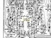
The 0.1uF ceramic capacitor in your picture does appear to be the C426:
3020B c426.jpg

And it is just filtering the +ve DC rail, a PPS film capacitor will work in this position, but its overkill to use a high quality film type here. IMO, a larger polyester film at C426 would be more appropriate. Note that the -ve DC rail is locally filtered by C417/C418, which are 47uF electrolytic capacitors.
 
Do you what you will, but I say there's close to 0% chance the polyester sounds better than the PPS you already purchased for this position. In my experience, the performance increase of swapping pps to mkt or mks is always the same; net nothing / net minus. It has never justified itself through my listening trials and board revisions compared with the better performing films available. In the end, it's just sound that matters. There's no such thing as overkill when talking cheap, superior capacitor materials like these small value potted film caps.

I've removed polyester in most instances where I used them when another, higher-performing film type was also available, as it always sounds better even when you think it should not be in a direct audio path. I've never felt the need to remove any PPS I've put in. They consistently sound more similar to polypropylene than polyester. I only use polyester when I'm replacing a small value electrolytic, and where a polypropylene is too large to fit. For such inexpensive, small values as 0.1uF you may as well use these better performing potted types; fkp2, pps, cbb, pfr, mkp, phe, etc. No reason to cheap out when the better choices are already cheap. Everyone has their school of thought, I tend to increase passive component materials that sound better (which were originally not included only because of addt'l production cost) while leaving original values the same as originally designed by electronic engineers more capable than I. Just my $0.02.
 
Thank you everyone for your time and contributions.
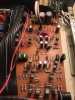
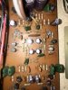
Am uploading the board, both sides, in the hope that it helps identification.

4E38C85B-ADF8-4E6F-ACEC-3936BD8D3672.jpeg CE6BFCFB-D6A5-4A6D-BC31-E777AFCCC7B5.jpeg
 
The recommendation of a polyester film capacitor instead of a PPS film one is to allow one to increase the capacitor size in a location with limited board space. I do not know whether the 0.1µF decoupling capacitor in the NAD 3020 is potentially a problem, but in some cases, a 0.1µF capacitor may be insufficient to provide adequate decoupling. Here is an example of such from Dr. Leach (https://leachlegacy.ece.gatech.edu/lowtim/pwrsply.html): "I have seen some circuits in which the values of the decoupling capacitors are far too small. When I first started designing the Low TIM amplifier, I used a single 0.1 uF capacitor to decouple each power supply rail at the points where they connect to the circuit boards, i.e. in place of C21 through C24. I used that value because I had seen it used in so many other circuits. In taking measurements on the amplifier, I found a very large AC signal would appear on the power supply rails when I tested the amplifier at high frequencies. At 1 MHz, the AC signal on the rails had the same amplitude as the amplifier output signal. When I removed the 0.1 uF decoupling capacitors, the AC signals on the rails would almost disappear. Replacing the 0.1 uF capacitors with 10 uF capacitors eliminated the problem. I settled on 100 uF capacitors to be on the safe side."
 
Forget the connecting 560 ohm resistors across R645/646, this is for the factory service procedure which requires you to juggle resistors in order to set the bias (and also assumes you have a limitless supply of different value resistors to place in parallel). You have fitted the Bournes trimmers which negates this. What I would advise is to replace R645/646 with 1K2 resistors like they used in the original 3020. You could leave the 180R resistors in place, but in my experience makes it a little harder to adjust the bias. In addition, most trimmers are shipped with the wipers in mid position. This could lead to the scenario where the bias is way higher than it needs to be when you first turn it on. Think about it. A 180R and a 500R resistor in parallel give 132 ohms. A 1K2 and a 500R resistor give 352 ohms. This gives you a little more adjustment in the trimmer. If you are going to use the factory procedure and add resistors, DO NOT remove the 560R resistors afterwards, as this will throw out your adjustments.

I would certainly remove and re-grease the output transistors. The old stuff has been there for 25-30 years, it can and does dry out. This is one of the first things I do whenever I restore an amp, and sadly something that I see so many other "restorations" skip out on. If you're uncomfortable cleaning and re-using the mica washers, use the silicone heatsink pads. If you do re-use the mica washers, do not use the CPU type heatsink compound as some of them conduct electricity. Use the Aavid stuff Mouser part number 532-250.

Setting the idling current won't make any difference to how loud the amp will go. Setting it too low will increase the crossover distortion because the output transistors will shut off as they cross over to the other half of the the audio waveform. Hence the term "crossover distortion". Idle current exists to cut down the amount of crossover distortion by keeping them slightly turned on at all times, hence the term "idle current". Setting the idle current way too high will make the amp run hotter as the transistors are kept turned on more, pushing the amp into running more like a class A amplifier.

I realize what I'm saying may contradict what others have said. My computer contains a folder with pictures of all my work, and there are 32 directories for NAD 3020 amps since 2015, that's a lot of restorations. I've never had one come back to me that wasn't influenced by outside interference (water damage, fancy speaker cables causing oscillation, shipping damage, LEDs too bright, etc), search AK for positive reviews if you like.

Lee.
 
Thanks guys, really helpful.
Lee, thanks for talking through the replacement procedure for the Bournes.
Attached is a photo showing where the Bournes and the 1K2 should be inserted please could you confirm?
IMG_7172 copy 2.jpg
 
Thanks Leestereo, it would appear that you've managed to identify C426, even though it's not printed on the board. Thank you!
Seems fair to say that it's easy to improve on the original ceramic currently occupying this postion.
Would be good to hear if others have achieved an audible difference in sound quality when swapping out the ceramics in this area in the unit?
 
Ok.
So have replaced replaced resistors at RX1 and RX2 with the Bournes trimmers.
Measured the resistance of the resistors upon removal, and before inserting the Bournes trimmers turned the brass adjuster until I had an identical resistance for each replacement trimmer. ( FWIW this was 398ohms on one side 410ohms on the other.) Voila, the idle current readings immediately read identically to the previous arrangement. Now I can adjust and match (or even unmatch..) at will. If I run out of turns the 1K2 resistors are to hand.
Must remember to resolder the solder bridge!
Thank you everyone for your advice and help. It all seems straightforward now, but it certainly didn't whilst I was trying to navigate it.
Now awaiting the arrival of ceramic replacements for the pre section.
 
I'm not sure what you ended up getting, but as a no-brainer approach, you can replace the SLCC's with MLCC COG/NP0 types, except in the tuner section, I would just leave those ceramics alone. These are more stable, better performing, and it takes the guesswork out of ceramic replacements. There will be a performance improvement, capacitance won't drift with temperature. These could also be changed out if you wanted. In no exact order, the general trend goes something like..

single layer ceramic < polar electrolytic < bi-polar electrolytic < polyester/mylar < polycarbonate < silver mica (best detail/ least bass) paper in oil, polypropylene/ polystyrene < teflon.

There are other types I haven't tried, but these are my personal rankings from what I've heard.

Silver mica is kind of in its own category, sounding different than film types, more similar to a brighter, more top-end heavy mlcc. The detail of the silver micas can be amazing but they are harsher and hard to live with most of the time and have weaker bass unless used sparingly and intentionally in an otherwise dull-sounding circuit.

The standard, green mylar chiclets you see in all the vintage gear are among my favorites for the polyester types. I've had a few instances where I thought they were better than polypropylenes I replaced them with. The ero mkt1822 is also not bad. Vintage ero and the yellow electrocube polyesters are among the better ones I've heard for mkt/mks types. The sky-blue russian "petp" is said to be another good sounding polyester that I haven't heard.

Pio, polypropylene/silver/gold/oil, polystyrene are my favorites. Teflons are sort of hard to come by and while some say technically better, can be large or expensive. You can source good milspec russian pio and polystyrene capacitors for cheap with long ship times from the usual suspect in online auctions. Teflons are also available from some of the same suppliers.
 
Last edited:
Thanks for the info and descriptions.
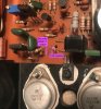
Well, in the case of my modest NAD 3020A I’ve ordered these, below. Only for changing the ceramics in the part of the amp shown in the photo.
2990774 5 RDE5C1H470J0M1H03A CAP, 47PF, 50V, MLCC, RADIAL RDE5C1H470J0M1H03A
2990778 5 RDE5C1H680J0M1H03A CAP, 68PF, 50V, MLCC, RADIAL RDE5C1H680J0M1H03A
2990741 5 RCE5C1H221J0DBH03A CAP, 220PF, 50V, MLCC, RADIAL RCE5C1H221J0DBH03A
25291631SMR5104J100J03L16.5CBULK CAP, 0.1µF, 100V, 5%, PPS,RADIALSMR5104J100J03L16.5CBULK
 
Mylar capacitor replacement.
I want to replace two pairs of these green ones with polypropylene caps for the phono path but need to know what values to order. The marking on the sides are:
00752J 50VF
.027J 50VF
Does anyone know what values these are and what I should be specifying for the order, ideally from
https://uk.farnell.com/
 
Back
Top Bottom