• Please note that Audiokarma will be offline briefly for updates early on Monday morning, September 28th.

NAD 3020A - ceramic disc cap replacement in pre amp

...I prefer polypropylene over multi-layer COG/NP0 types, but that's just my opinion. It may be closer to the original sound to stick with the MLCC's, but both types are a definite performance improvement...

C0G/NP0 types are very low distortion components; very much superior to garden-variety ceramics (even X7R types display relatively high levels of distortion) and comparable to polypropylene types.

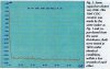
X7RDistortion_zpsdaf8c60c.jpg~original.jpg

C0GNPOCeramicdistortion_zps528e744e.jpg~original.jpg
PPCapdistortion_zps1d9623f4.jpg~original.jpg

All figures from the Capacitor Sound article by Cyril Bateman published in Electonics World (July 2002).
 
To maximize phono stage performance, the signal path electrolytic capacitors at the input and output of the stage should be upgraded to stacked film types, i.e., C401/C402 and C421/C422. The RIAA feedback components, i.e. C413/C414, C415/C416 and C427/C428 should be upgraded to polypropylene types and R419-R424 resistors to metal film types and lastly, the polarized electrolytic at C407/C408 should be upgraded to bi-polar type.
 
+1 on the idea of swapping out polarized electrolytics. I'd replace with bi-polar audio rated types such as Nichicon UES, UDB, or Panasonic SU. Better yet, you can replace electrolytics with films, the problem is that even a 3.3uF mkp is going to be absolutely huge and expensive. However, any small electrolytic like .047uF .33uF .47uF .68uF 1uF etc. should be replaced with polypropylene when you come across them.
 
...However, any small electrolytic like .047uF .33uF .47uF .68uF 1uF etc. should be replaced with polypropylene when you come across them.

Unfortunately, even polypropylene capacitors that are <1µF are quite large, e.g., a WIMA 0.33µF MKP (polypropylene) capacitor is comparable in size to a WIMA 10µF MKS (polyester) capacitor. In the attached picture, the 0.33µF MKP capacitor is significanly larger than the 3.3µF MKS capacitor.

MKP vs. MKS.jpg
 
Unfortunately, even polypropylene capacitors that are <1µF are quite large, e.g., a WIMA 0.33µF MKP (polypropylene) capacitor is comparable in size to a WIMA 10µF MKS (polyester) capacitor. In the attached picture, the 0.33µF MKP capacitor is significanly larger than the 3.3µF MKS capacitor.

View attachment 2165988

True. Depends on voltage rating though, and the trick with films is to find a way to obtain the lowest working voltage you actually need. A 1uF 63V mkp will be much smaller than a 1uF 1kV mkp but much harder to source. Most seem to be in the 100V+ category which is unfortunate and is often times more than we need unless dealing with tubes. The best hope are usually these potted types. It would be great if the industry made more of them with this narrow profile but even more vertical length to accommodate more capacitance. Most of the time I seem to have an additional inch (maybe two) of vertical length that I could use up inside the machine. Another option is to run an axial on its side above other components or on one end. Some circuits don't mind additional lead length, some do. I haven't run into any problems while keeping any exposed (longer) leads heatshrinked. Although in an ideal situation, you always keep your leads short as possible.
 
Do not replace polarized electrolytics with non polar electrolytics. The non polar caps are not as low impedance. Use Panasonic FC series caps. Anything from .01uF - 1uF can be replaced with polyester film. Anything below .01uF should remain ceramic for best rf properties.
 
Yes, original ceramics stay in the tuner section, don't touch them! We were just talking about the phono section. MKS would be a good call anywhere small-value electrolytics were originally used and larger MKP's won't fit.
 
In the meantime, I measured the idle current and, yes, it's
Left channel: 56.2mV
Right channel:36.2mV
Others have written that the amp sounds best with readings that have this difference (it's how NAD set it at the factory.)
Although I have appropriate Bournes trimmers to hand I'm tempted to leave the unit as it is for fear of messing with the 'magical' SQ.
Question:
I desoldered the solder links/blobs beneath R653 and R654 in order to get these readings..
Do I need to resolder the blobs?
What would be the likely consequence of not resoldering the blobs?
 
I have personally never read that NAD set the idle current differently for each channel at the factory. Nor have I read that the amp sounds "best" maladjusted in this way.

If you do not resolder the shorts across the 1 ohm resistors R653 and 654, all the current will be running through these resistors, and they will overheat and blow when the amp apporaches full power.
 
True. Depends on voltage rating though, and the trick with films is to find a way to obtain the lowest working voltage you actually need. A 1uF 63V mkp will be much smaller than a 1uF 1kV mkp but much harder to source. Most seem to be in the 100V+ category which is unfortunate and is often times more than we need unless dealing with tubes...

The 0.33µF MKP capacitor (8mm x 14mm x 7.2mm) shown is rated at 63VDC and the smaller 3.3µF MKS capacitor (5.5mm x 11.5mm x 7.2mm) shown is rated at 50VDC. AFAIK, the lowest voltage rating available for the MKP capacitors is 63V and the lowest voltage rating available for MKS capacitors is 50V.
 
MK
The 0.33µF MKP capacitor (8mm x 14mm x 7.2mm) shown is rated at 63VDC and the smaller 3.3µF MKS capacitor (5.5mm x 11.5mm x 7.2mm) shown is rated at 50VDC. AFAIK, the lowest voltage rating available for the MKP capacitors is 63V and the lowest voltage rating available for MKS capacitors is 50V.

MKT would work along with MKS if MKP are too large when replacing smaller electrolytics. Both of these other film types should be an improvement over e-lytics.

Here is the alignment procedure for the "3020". I couldn't find the "A" version but they may (likely) be the same adjustments, but I don't know for certain. You may want to double-check on the "A" service manual if you can find one.

It would be a necessity to at least get the idle current dialed-in if going to the trouble of carefully choosing all these caps for best sound and performance.

Odd idle adjustment procedure that I'm still wrapping my head around. Parallel two 560 ohm resistors across R646 for R channel and one 560 ohm resistor across R645 for L channel?

20210319_165717.jpg
 
All I can tell you is shoot for 40-45mV on both channels. The lower you set the idle current (within the normal 30-60mV range) the more usable movement you have on the volume dial before it begins to distort.
 
Thanks.
Yes, the option to dial in the setting does make sense... even if the ‘best’ sound (which I realise can be a subjective term) is achieved with settings that aren’t symmetrical. Personally, I haven’t come across this in any other amp, and instinctively it doesn’t seem correct. Maybe only some trial and error will discern this. Would be good to hear from others if, over time, they’ve arrived at an optimum setting for the 3020A.
Thanks again for looking up the manual. Yes, the adjustment procedure is quite unusual and eccentric..
 
It doesn't say anywhere the idle current should be different for L/R channels. According to the SM, it is 45mV avg. for both. It's just that there's an asymmetrical way of adjusting them to the get the same millivoltage (for some odd reason).
 
NAD 3020A

Preparing to fit the Bournes trimmers (3296Y-1-102LF, 1kΩ) but just want to be sure that I’ve got this right with this unusual arrangement..
Would greatly appreciate confirmation or otherwise from the wise.
Looking at the photo of my 3020A board attached below would the following procedure be correct?
- Wrap middle leg of newly purchased Bournes trimmer around end leg.
- Replace RX1 and RX2 resistors with these Bournes trimmers.
- With the solder join beneath the board at R653 and R654 in its desoldered state, take idle current readings at R653 and R654.
- Adjust the newly installed Bournes trimmers symmetrically to provide a reading of between 30mV - 60mV, ideally at the lower end of this range, on both channels.
- Resolder the solder join at R653.
- End.
IMG_7172 copy.jpg
 
I wouldn't install new trimmers right now. I'd hold off. You don't want to bite off more than you can chew and mess up all the progress you've already made on your project. The old ones are probably still fine, and just because bournes are technically better, doesn't mean the old ones need to be replaced. Before even attempting to install them, I'd be more focused on trying to adjust the ones you already have, but only if they sound out-of-whack.

If both channels sound good as-is, just leave them alone, unless you feel comfortable adjusting what's already there. If you can't adjust what's already there or don't feel comfortable doing it, don't attempt it because you'll never be able to dial in the bournes trimmers and it will sound worse than it does right now.
 
Thanks for the advice and appreciate the concern.
Should point out that there are no original trimmers remaining on this board. Bournes trimmers have already replaced the originals for adjusting DC and this has gone very well (0mV easily achieved on both channels.)
This venture would be embarked on in the expectation of having the option to adjust the idle current. It sounds great right now with its 56mV and 36mV readings, but without hearing it with both channels giving the same reading it’s a situation where one can’t know if an improved performance is being missed out on.
The person in post #30 seemed to take care going through a very similar process and ended up returning to his original set up. Even with the Bournes trimmers fitted, the original settings can probably be replicated if desired.
Bit of a conundrum but, as you say, would be a shame to spoil the stage to which I’ve now got it. Thanks again.
 
Did you remove the output transistors and put fresh heatsink grease on the mica washers? If so, what kind of grease did you use?

Your procedure above for adjusting the bias looks fine.
 
Hi Leesonic.
No I haven’t touched the original output transistors. (I know they’re original as I’ve owned the unit from new :) )
Thanks very much for confirming the adjustment procedure.
 
Back
Top Bottom