• The move to the new server is done. There are some software and database maintenance updates in process. This has us passing the hat around to help out. We appreciate any donations. Seriously, even a dollar helps. The payment page may be found here - https://www.audiokarma.org/support.html

Need help getting rid of hum

I believe it does, Tim. There is still some hum in the PHONO and TAPEHEAD positions (pretty bad in one channel on TAPEHEAD which normally would need attention, but since I won't be using it...), but in headphones, the true test, the hum is not significant until I turn it up to volume levels I would never reach. I'm ready to close out this thread. I suppose when I have nothing else to do I'll revisit the TAPEHEAD hum, but for now, 321 posts in one thread is enough.

Thank you for all your help and to everyone who has offered suggestions. Team Fisher Forum is the best. Thorne
 
I'm actually using Dave's revised values, but with components selected for availability. Dave's specified value for one of those resistors was 2.13M, which is not a thing you can get. I used a 2.0M in series with a 130k to get to the same place.
Same with those two capacitors in parallel. The 1100 in parallel with a 250 makes up the specified 1350pf with parts that can be gotten.

how you get there isn't too critical, just that the final value ends up right.
Are the numbers THAT critical? I built two 680pF caps in parallel to get 1360pF which is close to 1340pF, used a 360pF instead of a 350pF and a 2.1M resistor instead of 2.13M. Are those values too far off?

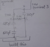
EDIT: Someone please check me... are my two 680's in series or parallel? I thought parallel but now I'm not sure and I'm wondering if series (which would make it 340pF instead of 1340) if a value that far off could cause hum.
upload_2020-6-17_9-48-17.png
 
Last edited:
your 680pf are in series to end up with 340pf. Don't think that it would cause hum but it would definitely screw with the EQ curve.

2.1M vs 2.13M are close enough I'd expect. The original value was 2.0M I think, so 2.1M is closer to right than the original. Exactly how much using different values affects things I don't know but the closer to specified values the better I expect.
 
Greetings, I think you should truly listen to Gadget in more than a few places within this thread. I have gone back a few pages and you said you re-installed the PECs for phono only. Why not jumper the now unused Tape Head connections so you can have two phono inputs ? Gadget and you already clearly identified which terminals go where. Gadget implied to make sure the Tape Head input jacks measure 47K to 100K Ohms per Tape Head jack. Standard RIAA phono input R is 47K, but some cartridges do like 68K or 100K Ohms as their input resistor.

Your pic in the post three above this, has no bass pole. Across the 2.1Meg, should be 1350 to 1500 pf if that was referencing dcgillespie's upgraded or original Fisher phono EQ. Why did you draw two 680pf in series across the 2.1 Meg ? That makes another 340pf ? Caps are additive when connected in parallel. EQ is not rocket science, but adhering to certain fundamentals is important. If we keep describing it and drawing it out for you and you install it incorrectly, perhaps you need to jump backwards and click your heels, then re-read all that was already described and ascertained ? We really do want to help you, but it relies on you to implement, unless you can find a local tech to come over to your workbench.

I have little experience with the Fisher receivers' PEC and the upgraded dcgillespie version. I cannot use the standard EQ math to verify these Fisher playback curves' accuracy. Usual RIAA active feedback EQ classic circuits have two R-C networks in parallel, which are series connected. As I described via PM, there is a feedback EQ start and a feedback EQ return. In between that goes a complete RIAA phono EQ network.

The stock PEC has only three connections per channel. The unique to Fisher network either works for you or you want better ? If the hum is only when you have the volume up, that is normal, very normal. Unused high gain inputs, like Tape Head or Phono need at least an input resistor (47K to 100K Ohms) at their jacks or the unterminated input will emit a loud hum. This thread has repetitious mentions of loud hum, some hum, minimal hum with headphones....However, you, Thorne, must make the choices to your liking. It has already been described how to make the Tape Hd input into another Phono input. If the standard PEC is agreed upon by fellow Fisher users to be very good sounding, why are you reinventing the wheel ? Why get loud hum while switching sources. Many preamp stages need a tt + cart connected to avoid hum. Same with Tape Head inputs...

As you have already realized, we all hope, is that switches, cartridge connections and input jacks which are a few years old can need attention, even when using known clean interconnecting cables. Shiit happens with vintage gear. Don't let that confuse you and then quickly rip out a circuit, please...only to connect some circuit back which you do not understand yet, or worse, reconnect with a brain fart error( as you have stated). Thank God you understand safety with high voltage devices. You do wear tight fitting leather, pigskin or deerskin gloves near the power supply, right ?

Okay, how about this ? Reread Gadget's sensible and informative posts to make the Tape Head into an extra Phono input. Then, re-study some RIAA or other phono EQ networks which you can then install, knowing the connections which you insist you knew. Once the noise floor is minimal, you can study up on other 12AX7 phono EQ circuits to implement. But, you must know the connections, as you mentioned you can do with this 500C blind folded. Then, you simply bypass the Tape Head or Phono PEC connections, remembering and drawing out their placement for further experiments, so you can refit your custom phono EQ. You have the resources and you can do this....
 
Last edited:
The revised EQ network came from Dave Gillespie's work of fine-tuning the stock phono circuit to improve compliance to RIAA spec. Its not bad stock but a few value tweaks makes it tighter.

relevent thread here
https://audiokarma.org/forums/index.php?threads/the-fisher-phono-preamp-and-riaa.600690/

The schematics are my drawing of both the stock network and the revised one. Slightly easier to see what changed here since both are drawn side by side in the same scribbly style. Basically 2 caps and 1 resistor have value tweaks, no major re-engineering of the basic circuit is involved.

index.php


The one at the bottom is electrically the same as the RIAA part at top right, just uses components that are a little easier to source but add up to the same total value. I also dumped the NAB eq part because I have no need for it.
 
I'll answer your questions. I don't intentionally ignore what people suggest.

"Where did the mention of 1340pf come from ?"
Look about half way down this post:
https://audiokarma.org/forums/index...er-phono-preamp-and-riaa.600690/#post-7919175
where it says "The 1800 pF becomes 1350 pF (two appropriate 680 pF caps in parallel)".

"Why did you draw two 680pf in series across the 2.1 Meg ?"
Not sure what you're asking. If you're asking why I drew two 680's in series, that was a mistake.
If you're asking why I drew them ACROSS (as in parallel) the 2.1Meg, the original drawing looks to me like a 1350pF is in parallel with the 2.1M resistor. Is it not a parallel connection when 2 sides of one component are connected to 2 sides of another component?

"That makes another 340pf ?"
No it doesn't. I thought I had the two 680 caps connected in parallel. I was mistaken.

"...re-read all that was already described and ascertained ?"
I can't count how many times I've reread my thread, the original thread about adding the RIAA mod in the Fisher 400 as well as several other posts in different forums about tracking down hums and dealing with EQ circuits in amps. I just don't always get it the first time and sometimes not even the 2nd time. Sometimes explanations I read generate more questions than they answer.

"The unique to Fisher network either works for you or you want better ? "
Yes I do. I'm an audiophile of sorts and little improvements do make a difference for me. Especially when the people whose work I respect announce publicly that they've found ways to improve these great amps. That's what the RIAA mod does according to frequency graphs I read.

"why are you reinventing the wheel ? "
I'm not the one who came up with the RIAA improvement. However, if I were to believe that I might have a design for a better wheel, I would make an effort to see if it really is better.

"You do wear tight fitting leather, pigskin or deerskin gloves near the power supply, right ?"
Not usually. I can't do detailed work while wearing heavy gloves. I'm very aware of where the high voltages are. Yes, I've had my share of accidents. I'd be surprised if there's a forum participant who hasn't. (OK, sure they may be some)

"you can do this."
Thanks if this is a genuine vote of confidence. The fact is I have done it except for having the 680's in series instead of in parallel. If such a gaffe can result in hum, that would be great to know. I'm a little burned out after 327 posts and the work they inspired. But I'm intent on understanding why this has failed for me. This follow-up work so far has brought good results - I discovered I did the wrong math and I connected the 2 caps incorrectly. So I already may have fixed my problem. I'll keep investigating. I'm very hungry to learn.

Thorne
 
Thorne, I am only trying to help, as are other contributors. There is no need for explanations. I do really think you can do this. Explaining or discussing does not help your cause of learning and understanding phono playback curves or circuits. Truly, as I mentioned in PM, re-reading over and over means more than a second or third time until your confidence is built and your implementation is correct. I only intend to have helped you...


Excellent Gadget ! Still, there is no standard, easy way to mathematically confirm the RIAA circuit. Note the original 390 pf or Dave's 350 pf treble rolloff cap is connected across both the treble rolloff resistor and bass boost networks. That is where the math fails. Also, the NAB network is an (NAB, National Assoc. of Broadcasters, later the NARTB) Tape Head network. With RxC = Time Constant, in uSec. .00035 x 270,000 does not equal the RIAA 75 uSec. spec. for treble rolloff. It yields 94.5 uSec, which indicates excessive treble rolloff. Trying the two resistors in parallel x .0035 = 84.5 uSec. which is still excessive, indicating mellow highs. Using the factory's 390pf would result in even higher uSec. Eventually, I would like to know the mathematical computation Fisher and dcg and George intended. I had similar perplexed results deciphering earlier Fisher phono EQ networks

Gadget, your modified version should make it easy for Thorne to make the Tape Head input into an extra Phono input, as long as he also ascertains 47K to 100K at the Tape Head input jacks, when switched in...
 
Last edited:
what he said. NAB / NARTB. its tape head EQ. Tapes also have an EQ for recording, similar but not identical to records. Unless you've got an old tape machine without an internal preamp, its not a useful input. Most tape machines made since the mid 60s or so have internal preamps and just need a line-level connection.

Still, there is no standard, easy way to mathematically confirm the RIAA circuit.
Its a feedback EQ rather than a passive one. guessing thats why the usual math doesn't work?
 
Well having a TAPEHEAD input is about as useful as having 2 PHONO inputs at least in my case. I'm not a DJ and if I were I don't believe I would bring a Fisher amp to rock the audience. :music:

So now that I figured out and fixed my RIAA network issue, I tried once again to accompany the PEC's, lead 3 tied-off. Added the RIAA first on the left channel - sounded superb, very little hum. OK, keep going ! Repeated the install on the right channel. Ugh, mucho hum. I metered the resistors - all values the same. I metered the PEC leads in all possible combinations - all values the same. For now too lazy to unsolder a lead and meter the caps. I probed all the leads and components looking for loose/bad connections. All good. I played a record - sounded great. Couldn't really hear the hum... but knowing it's there drives me to solve it. "I can do this"

EDIT: Come to think of it, this is exactly what happened the last time I installed the new RIAA. The first one went in with no problems and sounded fine. But after adding the 2nd one, the hum was back. Interesting. And the hum is on the channel I had previously installed ! Weird.
 
Last edited:
Thorne, You are so close...Keep on keepin' on...Perseverance will pay off...

  • Gadget73, Analyzing and upgrading active feedback networks is a passion of mine. With the 390pf or 350 pf across/in parallel with the bass pole plus the treble pole resistor is the misleading factor. If anyone wants to read the seminal phono preamp playback curve EQ treatise, complete with trigonometric analysis of any type of EQ, passive or active, check out the Journal of the Audio Engineering Society (AES), June 1979, Vol. 27, issue #6. Stanley Lipshitz authors, later assisted by Walter Jung, two legendary audio engineers. Some of the best active feedback phono preamps can be verified accurately with this algebraic formula:

  • (R1 x R2) divided by (R1 + R2) results in a multiplier, then multiplied by (C1 + C2). Thinking of parallel resistors, they are considered "product over sum." Likewise, the caps being additive, are considered parallel caps.
  • The multiplier multiplied by (C1 + C2), results in a Time Constant, in uSec. representing the actual Turnover frequency.
  • Finally, the mathematical constant of 159,155 (uSec. for 1 Hz) divided by the derived Turnover in uSec, yields the actual Turnover in Hz, which is 3db above the 0db reference at 1KHz, beginning the upward slope toward the bass boost of the playback curve.

  • Each network "pole" as in the bass boost network or the treble rolloff network also has a TC (Time Constant) with simple R x C = TC in uSec. then divided into the 159,155 to arrive at the Bass boost peak and Treble rolloff frequency transition points within the playback curve. These transition points are known as asymptotes.
As an example, let's see an excellent RIAA EQ circuit destined for upgrading Dyna PAS, Eico HF-85, HF-81 phono stage, the little chrome cutie Shure M-65 Phono preamp and other stereo dual 12AX7 preamps which have both tubes using cathode resistors. In this notation, // means "in parallel with" while & indicates in series with...:

2700pf // 2.2Meg Ohms & 815pf // 92K Ohms. Mathematically, (2,200,000 x 92,000) divided by 2,292,000 (2.2Meg + 92K) = multiplier 88,307.155
Then, 88,307.155 multiplied by .003515 (C1 + C2) = 310.399 uS. 159,155 divided by 310.399 = 512.74 Hz, which is nicely close to the RIAA spec of a 500 Hz Turnover.

Let's examine the R x C for each pole : Bass: .0027 x 2,200,00 = 5940 uS. 159,155 / 5940 = approx. bass resonance at 27 Hz, lower than the RIAA 50Hz spec. With low value coupling caps, like .025 to .047uf, this works out very well, in circuit...with outstanding bass measurements and sound in my Eico HF-85.
Treble: .000815 x 92,000 = 74.98 uS. 159,155 / 74.98 = 2122.6 Hz, seriously close to the RIAA specified 75us or -3db freq of 2122 Hz.
BTW, the above network values are similar to George's Regenesis retrofit to his reference PAS experiments.

Now, if we were to use the network values of Fisher's 500C phono EQ or dcgillespie's Revised Fisher phono EQ circuit, I am afraid you might be disappointed with the results. The treble will imply extra rolloff and the bass will appear, mathematically slightly soft. However, in circuit, it can certainly sound lovely and the playback curve can measure within the original RIAA spec's tolerance of + or - 2 db from 30 to 15,000 Hz, possibly even measured from 20-20KHz.

That is it for me tonight. I can edit and add more later. I just wanted you all to see the analytical algebraic math involved which verifies RIAA adherence. RIAA originally specifies 3180 uS for bass, 318 uS for Turnover, 75 uS for Rolloff.

 
Last edited:
To be honest, when I posted "sounded superb", I wasn't commenting on frequency representation. I was commenting on my plague - the hum - and how it "superbly" disappeared in the one channel.

I've always enjoyed math (I was skipped from 10th grade to 12th grade math by my advisors). I still do some math on paper. Your analysis, Tube, certainly is a deep dive. I've done simple Time Constant math with my phase inverter coupling caps to get as close as possible to 75uS (and also time constant math with the FM mono and stereo de-emphasis). But that's only an RC network (t = RC).

What is a "pole" in your discussion?
And what is the component circuitry that necessitates that math? I mean I know it's a cap in parallel with a resistor which together are in series with another cap and resistor in parallel, et cetera. But is that some kind of standard circuit for crossover networks or something?

EDIT: I discovered that over time the MPX separation control has moved, probably from my grabbing the chassis to move it around. Luckily I have a picture of the way it was after Dave fixed it for me way back when.
 
Last edited:
OK, I edited the phono playback EQ post above, which implies that within the overall feedback EQ network, there is a Bass Boost network pole connected in series with a Treble Rolloff network pole. While the math used can be considered a “deep dive,“now you realize why reading electronic essays can require re-reading, again and again.
 
Yes, Gadget, some of us have too many tables. I have at least two connected and a third nearby for my workbench system. There are another three by the main system.

This brings us to the need for a second phono input for Thorne, so he can prototype which phono network he prefers. Between each PEC Terminal #3 point, the “start” of the feedback, and terminal #1, the “return” of the overall feedback network, lies an internal, factory Fisher phono EQ circuit.

If you know where the PEC terminal 2 was connected, by bypassing the internal Tape Hd. circuit between terminal 2 and 1, you can insert your own trial phono EQ circuit between the terminal 2 connection point and terminal 1 connection point ! You can thus prototype a different circuit and then decide which Phono EQ you prefer, simply by swapping the table cables between Phono In or Tape Head In and switching the selector switch, with volume down to avoid noise. Which circuit you choose is deserving of another post.

Of course, Thorne needs to sort out the humbugger, first. The hum can still be something as simple as an oxidized connection on the selector switch or even in or around the RCA jacks and plugs, as well as cartridge connections. These oxidized connections are not easily seen with our eyes. We are cheering you on, Thorne...
 
Last edited:
Finally figured it out. There still is hum, even with a TT connected to the inputs, but I believe it's as low as I'll get it and what's new is that I have both RIAA networks connected and the hum isn't any louder than without them. It turned out that I had one leg of the 2.1M resistor connected after the 360Ω instead of before. Sometimes it's the simplest things.
 
Thorne,

With it selected to phono and the shorting plugs in, do you still hear hum? I'm wondering if the remaining little bit of hum is coming from the TT?
 
Back
Top Bottom