
• The move to the new server is done. There are some software and database maintenance updates in process. This has us passing the hat around to help out. We appreciate any donations. Seriously, even a dollar helps. The payment page may be found here - https://www.audiokarma.org/support.html

Need help getting rid of hum

Thanks, Larry. The IBAM power line comes from V14 pin 4 and is wrapped around the metal tube that houses the TAPE HEAD and PHONO LOW lines to the selector switch. The IBAM board is external and the lines go through the chassis holes around capcan C92 which is inoperative. That should be OK. Although when I move my hand near those metal tube lines, the hum gets real loud. I don't know why.
 
IBAM POWER should be coming off the DUAL BIAS CAP. Tapping off the paralle/seriesed tube heaters is bound to cause imbalance in voltages between the tubes. V14 is all the way in the front of the unit. IBAM is all the way in the back. Unshielded DC power lead going thru the IF section, then in, thru and around the preamp?!?!?! Shorten up that lead and plug it in to the NEGATIVE TERMINAL on the BIAS CAP. or the -25V BIAS Tap on the SDS Board.

Also if you wrapped the phono/tapehead shield tube, It probably doesn't like it. ReRoute the line and keep it away from the shield tubes.
 
Last edited:
Larry - We went thru this long ago. Because I have the SDS board, you had me find the filament lead (which I recently measured at -22.7v) on that board and use that to power IBAM. The filament, as far as I can tell because the lead emanates from underneath the SDS board, goes immediately to V14 pin 4. The wire is inside a yellow insulation with a black stripe and has a ground connection too. The next stop for that white lead after V14 pin 4 is to V17 pin 4. And that's where it terminates.

Maybe I'm not understanding what you mean by DUAL BIAS CAP. I don't know of anything by that name. In the power section where the SDS board resides, everyone told me NOT to locate the IBAM power lead. So I'm puzzled as to where to find IBAM power that's closer to the output section.
 
Disregard my last. On the lead from the SDS board to V14, you didn't happen to ground both ends did you???? If so disconnect hte ground wire from the chassis and cut it off short where it goes into the cover sleeve. Grounding both ends can/will cause a ground loop and hum. Plus unwrap the lead from the metal shield tube and reroute it away from there.

DUAL BIAS CAP is original equipment. It's that big orange cap(upper left corner) underneath in the photofact.
 
The filament from the SDS board does have a ground lead inside the YEL/BLK and it is connected to ground near V14 on a t-strip. However, I cannot tell if it is grounded at the SDS board as the wire is underneath the board. Would it be OK to try clipping the ground near V14 ? I suppose if it's not grounded at the SDS board, nothing bad will happen. If it is grounded at the board, will anything bad happen?

I am unwinding the leads from around the metal tube now. I will owe you BIG TIME if this fixes the hum. (Not that I already don't owe you and others already).
 
The hum is significantly reduced by unwrapping and relocating the IBAM power and ground leads !! WOO HOO ! There still is some hum, but music may drown it out. I relocated the power lead to V17 pin 4 which is the next stop after V14 pin 4. The ground was relocated to a grounded t-strip terminal close to the output tubes. Much shorter.

I'm scared that clipping the filament ground lead may make the chassis into a shock machine. Is that silly?
 
Last edited:
The reason for one end only grounded is to prevent ground loops. With one end grounded it's a shield. Go ahead and snip the ground on the lead from the SDS board. Then use your Ohm meter to check for continuity between the remaining ground wire (going to the SDS board) and chassis. If it shows close to ZERO Ohms it's connected, if it shows open then it's not connected at the SDS (in this case re-connect the end you just snipped). You don't want both end connected.
 
I set the meter for continuity, black lead to chassis ground, red lead to the clipped ground connection in the YEL/BLK wire. The meter sounded continuity and displayed 15 ohms. So the ground WAS connected at both ends. I left the ground clipped and checked the hum. Results coming here....

Hum is virtually gone !!!! Larry, I love you (in an electronics sort of way you understand). THANK YOU !!!

Next...the test with TT connected and playing. But it's gonna be heaven !
 
Last edited:
PS - Tube V17 was out of the chassis when I did the testing. Hmmm. And that's where the new IBAM power lead is connected. Hopefully it doesn't matter. I'll post here if it does.

Major problem... I powered up, tested the current on the output tubes. It jumped from 33mV way up to 48mV ! I was able to turn them all back down to 34mV except for V11 which won't go below 38mV. Oy. Is this because I moved the IBAM power lead from V14 to V17? Even at 38mV that's still only 15 watts which isn't bad and actually sounds better with more punch and bass. But I don't want to burn out those great old Westinghousers.

I should state that I also replaced the 10 ohm resistors at the output tubes pin 5. They were 5% and I replaced them with 1%.

Well, I spoke too soon. The hum is still there though definitely less. Crap. Tried with headphones and it is really significantly better. :)
 
Last edited:
Take out the power tubes, power up and take voltages on Pins 4 and 5 (referenced to chassis) on V14 and V17 They'll be one of 3 voltages. About -24,About -12, or 0. Connect to the one that gives you -24 or so. Pretty sure the reason the bias climbed is that you changed the bias input voltage off the heater pin by going from V14 to V17. Going toward 0 volts results in a higher bias reading at the tube. Note on the Schematic that V14 and V15 are in series and are in parallel with V16 and V17(in series). -24 volts in, zero out, with 12 or so in the middle between the tubes. You want the BIAS Lead on the highest reading tube pin (4 or 5 on whichever pair of tubes)
 
That analysis didn't help because moving the IBAM power lead from pin 4 on V14 to V17 made hardly any change:

V14 pin 4 = -19.5v
V14 pin 5 = -9.5
V17 pin 4 = -19.6
V17 pin 5 = -9.7

Does the parallel/series point you made make a difference? The measurements don't seem to. Maybe it wouldn't hurt to move the lead back to V14 pin 4 though I have a feeling it's something else since the voltages at pin 4 on the 2 tubes is pretty much the same. I don't believe the changed 10 ohm resistors could have made that difference. I also tightened some power tube pins, but I don't believe that could account for the difference. Same thing with moving the IBAM ground lead.

I think I found it. The 1200 ohm 10 watter came loose on the V9 pin 1 power tube. Would that do it?
 
Your heater/BIAS voltage is way too low. It should be in the range of -22v to -24v. You're tubes are starving and taking a longer time to heat up (which they never do fully). This can cause increased distortion in SQ. Also with a lower BIAS Voltage, for a given tube, the ma's will go up. It doesn't make a difference whether on V14 or V17, as long as the supply to the IBAM is the FULL voltage on that circuit.

This is why your adjustment is two blocked, not in the middle of the pots. Bring the voltage up to -23 to -24v and that should take care of the tubes starving and the IBAM Adjustment. The SDS board may need some work or parts.

The 1.2K 10w being loose will affect the screens voltage on the tubes. Which in effect screws with the whole tubes operation (Dave can give you the Websters Version with all the BIG Multi syllabic words;)) and can possibly kill the tubes. BIAS / HEATER Voltages are on a different circuit. Resolder the 1.2K 10W and test your voltages again. If they are still low (check all that you can downstream from the SDS at the 1st connection for each circuit) you got a power supply problem.
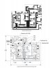
This is one of the reasons I don't like the SDS Board. 1.) it gets HOT, which cooks the caps, resistors, et al. 2.) NO Ventilation around it (see #1). 3. Repairs are a Royal PITA!. And to repair it you have to think outside the schematic.
 
Larry - I agree 100% about the SDS board. I'd be VERY willing to dump it (for the exact same reasons you cite) and replace it with a more accessible, revamped power supply though I would need help with the parts and installation. I've seen plenty of revamped power supplies online so I know what they look like, just not part specs. Can you refer me to something?

As far as the current, the measurements I posted above were after I resoldered the big resistor. I checked the IBAM board and still have the same issue - cannot get them below 37mA and V11 is all the way down on a 24-turn pot !

You say my output tubes are starved. What is it for which they're starved? I thought that since I was dialed in at 33mA and voltage to the tubes was 398v that I was spot on with everything about the output tubes. Actually I was worried that 438v out of pin 3 on the tubes was too much. I know that -19 is greater than -24 so I don't understand why you say it is "too low."

The big question... How do I remediate to solve the "starving" issue? I've read about this issue and remember that I may have to add a resistor somewhere? I think at this point I'm going to move the IBAM power lead back to V14, see if that fixes all this. These numbers are drastically different from measurements I took on May 11. Something went wrong. Or the May 11 measurements were on a 120vac line. Could that difference in AC voltage (110 vs 120) account for the variations in measurements? Normally the 500-C gets powered from a power strip whose voltage I have set at 110vac.

Could it be the metal film 10 ohm 1/4w 1% resistors I put at all pin 5 of output tubes? I assumed metal film would be OK. I read up and believe metal film is a better choice for a few reasons.

Here are all the voltages coming off the SDS board (see attached parts image):

A = 335 vdc (spec = 430. this worries me) goes to left PI pot, center terminal.
B = 356v (spec = 375. under spec) goes to daisy-chained pin 1 of output tubes.
C = 397v (spec = 350. over spec) goes to t-strip terminal where R143 non-tube side is connected.
D = 299v (spec = 295) goes to orange wire to MPX power supply.
E = 208v (spec = 215) goes to purple wire where R22 and R19 meet which connect to V17.
filament = -17v (that's worse than -19 I measured before, eh? no spec for this part)
filament winding @ 8.2 ohm 5w resistor = -6.76v
D1 = 396v at stripe side; 197v other side. 197v is the R/Y transformer lead.
D2 = 197v at stripe side; 0v other side.
C14 = 197v in; 0v out
R2 = 183v on one side; 190v other side.
R3 = 190v on one side; 197v other side.

V14 pin 4 = -17v
V17 pin 4 = -17v

output tubes:
pin 1 = 356v
pin 3 = 390v
pin 4 = 354v
pin 5 = 373v - 381v
pin 6 = -16v
 

Attachments

  • SDS board parts.JPG
    SDS board parts.JPG
    82.5 KB · Views: 9
Last edited:
Crap. After I soldered IBAM lead to V14, measurements are same as in post 77. Guess it wasn't fully connected when I tested in post 79. I need help.

EDIT: It's not V14 versus V17 that makes the difference. It's the AC voltage, 122 versus 110. When I use 122 vac, I get -19vdc. With 110 vac I get only -17vdc. So is it that I've got my 500-C setup to run on 122 vac? No, because now my output tubes pin 5 voltage is 0.42 and I still have V11's IBAM pot all the way down and can go no further. What the hell went wrong ?!

EDIT2: I measured C51 and C57. C51 is supposed to be 2uF. It measured at 1.4uF while still connected in the circuit but with power off. C57 is supposed to be 0.5uF but measured 9.2uF. Is C57 cooked? I'm guessing I may have cooked it while soldering the new 10 ohm resistor on V10 which is where C57 is connected - they share the ground at V10.
 
Last edited:
Back
Top Bottom