• The move to the new server is done. There are some software and database maintenance updates in process. This has us passing the hat around to help out. We appreciate any donations. Seriously, even a dollar helps. The payment page may be found here - https://www.audiokarma.org/support.html

Need help getting rid of hum

Tony - Thanks for offering. I think I have all the pics of the front I need. Let me ask this... If there's a yellow with black stripe wire emanating from underneath the board, is it connected at V14 pin 4 and does it have a ground lead that connects to ground near V14? And if so, would you please test that V14 pin 4 has continuity with chassis ground. Thanks, Thorne
 
If package comes tomorrow I'll most likely open it up then and I'll check.

I have a 800c so some placements might be different
 
Thorne. In the Normal Factory Setup (400-500-800c) the Yellow/blk (sometimes wht/blk or other color combination)Filament supply has the shield grounded ONLY at the tube. I've done too many 400's and 800's to not know this. In the 500c the tube numbers are different from the 800c but the circuits are idnetical (except for the lack of AM). The bare wire in the Filament lead is for RF Shielding only. If it's connected on both ends, you end up with a ground loop/hum. Me thinks you've got some wiring mixups as the shield shouldn't have any bearing on voltages. I'd look seriously at the wiring and connections on the IBAM. It's a possibility that you changed something inadvertently and it's actually causing the voltages to go haywire. But the Heater Filament supply lead gets grounded at the tube for RF Shielding only. It DOES NOT get grounded at the SDS Board.
 
Thanks so much, Larry. I thought everything was working fine until recently so I would guess it's something I did recently but not the IBAM. Recent mods have been

- replacing 10 ohmers on output tubes,
- paper-in-oil caps in PHONO section,
- Sonicaps for phase inverter coupling caps,
- FM mono de-emphasis,
- of course replacing the detector IF amp,
- allowing for 12AT7 tubes in the MPX,
- revised noose on both channels (neither with the heater upgrade),

and that's pretty much it since January of last year.

Frankly I don't know when the hum became a problem. But if it's the YEL/BLK lead issue that's causing it, then I would suggest that I clip the ground lead and figure out the voltage issues after I replace the C51/C57 caps. Thanks for all your help with this. Thorne
 
Last edited:
Larry, The other thing I don't understand is how a wire can act as an RF shield. It's not the kind of wire that is wrapped around the "+" wire. It's a solid wire just like the + lead. Does that make sense?

I do agree that it makes no sense that clipping that ground lead should cause the voltages to go haywire. I cannot make any logic out of that. So maybe THAT is the issue I need to track down. With that lead clipped, the SDS board's voltages go way down. How would an inoperable ground lead cause such behavior? That's a mystery.

I've done a lot of reading today and I read an article that did say that B- does get grounded. Isn't a filament considered B- ? I would think that if that is incorrect that tubes and circuits all over the 500-C would have failed because I verified that the filament lead and that ground lead are indeed connected and I think it's done under the SDS board because I stripped away a good inch of insulation on that YEL/BLK and I cannot find anywhere that the 2 wires touch. There is no melt which I originally thought I must have caused. And like I said, the schematic shows that after those 4 tubes get their heater supply, the circuit is grounded. Am I reading the schematic incorrectly?

When you say "grounded ONLY at the tube", what exactly do you mean? Do you mean the ground must be ON the tube and not NEAR the tube? I don't doubt your expertise. I just want to understand. I looked for other 500-C chassis images to day and I found one that shows that yel/blk lead and it has the ground wire that is connected the same as mine. Let me go attach it if I can find it again.

Anyway, these are the latest readings and they look OK, don't they?

Output Tubes:
pin 1, SDS-B = 402 vdc (spec = 375)
pin 3 = 441 (plate, schematic = 430)
pin 5 = .341 (IBAM-adjusted)
pin 6 = -21
SDS filament (V14 pin 4) = -22.8
SDS-A, PI pot middle terminal = 378 (spec = 350)
SDS-C = 445 (spec = 430) goes to R143.
SDS-E = 230 (spec = 215) Goes to junction of R22 & R19.
SDS-D, B+ to MPX = 336 (spec = 295). After the 12AT7 enablement = 138 vdc @ MPX coil
SDS-F (just found this one) = 205 (spec = 160). Goes to R80.
 
Last edited:
All your voltages are proportionally high, which tells me that it's most likely ok. Your filament voltage per tube (of the 4) is approx -11.4vdc (GOOD NEWS). SDS F has 2 voltages (read the notes next to Swtich Position box on the schematic). 160V and 200V. 200V is in a SOLID BOX. This denotes that the voltage on "F" is 200V when in "AUX". NO BOX means in FM. Dotted Box means in FM MPX. I presume you are testing with the selector in AUX?

The B- from the SDS board does TWO things. It powers the IBAM and powers V14,15,16,17. V14 and 15 are in series as are V16 and 17. The 2 pairs are paralleled. Start at the Junction of the Yel/BLK wire to the 1st tube(V14?) There should be a wire that goes to the V16/V17 pair. Follow that from Pin 4 to pin5 or vice versa on that 1st tube, then thru a jumper to the 2nd tube. Follow pin 4 to 5 or vice versa (it actually doesn't make a difference which is 1st or 2nd). The output pin will be either grounded to the Tube Socket Frame thru both rivets (same thing with the V14/V15 pair.)

When I say at the tube, I don't mean on the tube but in the immediate vicinity of the tube socket. There should be a lug next to the socket or a Terminal strip that has a convenient ground lug. The reason for the RF Shielding is it's a DC Circuit running in, around, over and under and thru, both ACV areas and RF/IF areas that can affect it. The shield wire will drain off the interference to chassis, hence no RF Hash in the DCV and little to NO AC Hash either.

As for the bare wire in the YEL/BLK. It's an RF Shield only. It doesn't matter if it's a braided outer covering or a single strand running in between the inner wire and the outer jacket. As long as it's connected to a ground on ONE END ONLY it's a RF Shield. IT WAS NOT Designed to act as a Circuit ground. If used as such, it WILL cause a Ground loop, and possible hum. The HTR circuit is grounded at the last tube sockets in the strings.
 
Ah OK. I know about ground connecting at only one end. I've done that with my guitar rig setup. It's exactly how to get rid of hum when unbalanced cables are in the rig and there exist balanced (TRS) jacks at the receiving end with which to connect everything. Just as you say... ground at sending end, leave ground unattached at receiving end.

I need to figure out how to track down from where the hum originates. I have the tools. I just need a plan. I've read and read and read and all I can figure is use a scope and look for bad sine waves. I tried that and posted my results. But I don't know that I did it correctly nor if I interpreted the results correctly. If you have a minute, can you look at post 58? The way I view threads (as many posts as possible on one page) it's on page 3.

You said the B- does 2 things. The first is to power those 4 tubes. What is the 2nd thing? The RF shielding?

OK. I'm not giving up. I love this receiver too much. Wifey wants me to take it to HV HiFi. Waiting for his reply.
 
I removed C51 and C57. C51 was actually a 3.3uF, not 2uF per the schematic. Close enough I guess. So the measurements were not out of whack. Oh well. I'll replace them anyway with film caps.
 
Have you had the SDS board lifted at any time? I'm wondering if R85 & R120 got ungrounded (one of them) somehow? This would cause a hum before the volume due to imbalance in the circuit. I'd lift the board enough to check, and while you're at it, check the grn grnd at the board for a cold solder joint.
 
Well, I've been unable to get the board detached much more than about 1/2" because of wires either holding the board down from the underside or other components that prevent lifting it out. But I believe it's time that I get the board out and take some pictures. Right now I'm reinstalling caps. Back in a while.

EDIT: New C51 and C57 are in.

Green ground at SDS is on TOP of the board and is connected well. All of the SDS OUTs are on top of the board except for the filament. There are 2 red wires from the power transformer, labeled R and R/Y, that connect under the board at its top edge, well-connected.
 
Last edited:
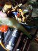
I followed a white wire that went under the board to the front preamp tubes. Not sure of pin number but here is a pic. There is also the ground wire from the top of board that goes to one of the radio tubes.

20200522_143509.jpg
 
Thanks so much, Tony. I've got the board separated as far as possible right at this moment so I'm taking lots of pics of the underside and the chassis underneath. For now, If you can trace all the wires coming off the SDS board and document to where they go, including any ground leads, that would be great. As far as I can tell there are leads A thru F, a GND and a FILAMENT, TRANSFORMER R and TRANSFORMER R/Y, all accessible on top of the board. If you also can include any caps or resistors that are in proximity to the SDS board, that would be great too. There may be a large resistor next to the chassis wall that connects to the top of the SD board. Let me know the specs of it.

Man, thank you ! Thorne

EDIT: That white wire, if the same as mine, goes to V14 pin 4. It might be the filament lead. Does it also contain a ground lead or just a single wire to the tube?
 
Last edited:
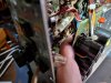
This is as far as I can pull out the SDS board because there is an 8.2ohm 5 watter that is soldered to chassis and SDS board, preventing pulling the board farther away.

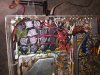
Here are the best pictures I got of what's behind the SDS board. It looks like there are C86, C103, R149, R85, R120 and R144. CR5 and CR7 are gone. C91, C98, C97, R135 and C92 are present but inoperative, all functions replaced by parts on the SDS board. C102 seems to be gone as well as R1, R2, R131 and R132. CR6 and R142 seem to be on the SDS board.

That grey cylindrical fuse-like part is I don't know what. I think there's something wrapped inside it. It's connected to the left-most t-strip terminal of the 5-way t-strip which a stock chassis has for R131 and R132. It's other end is the thin blue wire that connects to C10 on the SDS board.

The thin blue wire is connected to SDS cap C10 which then connects to C86. C86 connects to the left-most t-strip terminal where there is also a white wire which used to connect to (before I clipped it) the grid return resistors, R121-124. R131 is connected to something I cannot see, perhaps the 3rd from left t-strip terminal on the 5-way t-strip where R120 and R85 are connected. R120 and R85 connect to C102 and C102's other end is connected to the fuse it looks like. The only other remaining part I see is C86 whose other end connects to a vertical 3-way t-strip to which incoming AC is connected.

2 white wires from the power transformer connect to that 5-way horizontal t-strip, the 2 right-most terminals. They connect to green and brown leads that go to various other areas of the chassis.

There are 2 orange wires emanating from the other side of the power transformer that connect to the bottom (or right side of the chassis depending on your vantage point) of the SDS board, to the rectifier and 8.2ohm resistor I'm guessing. I can't really get the board pulled away enough to see.

I think that's about it for underneath the SDS board. Does it give a clue to anything?

 

Attachments

  • 0522201437a_HDR.jpg
    0522201437a_HDR.jpg
    111.2 KB · Views: 10
  • 0522201436b_HDR.jpg
    0522201436b_HDR.jpg
    95.8 KB · Views: 8
  • 0522201316_HDR.jpg
    0522201316_HDR.jpg
    106.4 KB · Views: 8
Last edited:
Not enough visible to make heads or tails of it all. Looks like a Rats Nest under there. That .01 600v cap is either C102 or C103. Can't tell from here.
 
Larry - Mia culpa. I now believe it's C103 judging from to what it's connected. I believe C102 was removed. I'll update my previous post. I'll see if I can do better.
 
Not much connected to underside of SDS board. 4 wires from power transformer, the B- lead and the connection to C103.
 

Attachments

  • 0522201735.jpg
    0522201735.jpg
    76.6 KB · Views: 4
  • 0522201735_HDR.jpg
    0522201735_HDR.jpg
    70.4 KB · Views: 2
  • 0522201736_HDR.jpg
    0522201736_HDR.jpg
    59.2 KB · Views: 2
  • 0522201739.jpg
    0522201739.jpg
    64 KB · Views: 2
Last edited:
Back
Top Bottom