• The move to the new server is done. There are some software and database maintenance updates in process. This has us passing the hat around to help out. We appreciate any donations. Seriously, even a dollar helps. The payment page may be found here - https://www.audiokarma.org/support.html

Need some input on Dim bulb tester behavior

All 4 of them made a short beep when measuring "Reverse Bias", so are all bad?
Beep should be continuous while probes are connected though may depend on meter.

What's worse is I believe I saw a spark from Q424 when I moved one of the probes.. takes a toll on the confidence..
(Is this a certain sign that I destroyed the Output?)
Probably shorting the transistor collector to chassis, no certainty you destroyed anything except an upstream fuse.
The shorting current does not pass through the transistor so you may be ok. Check for blown fuse.
 
A short beep and resistance statting to increase is caused by the large filter capacitors getting charged. Large capacitors are like a short circuit for an instant.

I'd say if the DBT stays still dim, and you can adjust the bias current (responding to adjustments), the amp is not shorted.

I'd measure the DC at the output. If less than 50mV, I'd say the amp is healthy enought.

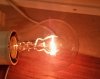
It would be good to see a picture of the DBT, to see how bright is it now. "Not too bright", "quite bright", "dim", are all subjective terms. Some amplifiers draw some significant current even at idle. (I've tested a Crown amp that lights a bit the DBT when it's OFF, barely orange, but you can see it)
 
Probably shorting the transistor collector to chassis, no certainty you destroyed anything except an upstream fuse.
The shorting current does not pass through the transistor so you may be ok. Check for blown fuse.
That was a relief, phew. I checked the two fuses that I could see and they seem to be ok.

A short beep and resistance statting to increase is caused by the large filter capacitors getting charged. Large capacitors are like a short circuit for an instant.
Thanks for clarifying, I think I need to educate myself a bit more on DMM/continuity so for now I´ll leave the transistors.

So as it is now,
  • I'm able to adjust the bias.
  • Speaker protectors gives a continuity (long) beep on DMM as well as the fuses.
  • The DC at the output (=DC offset?) is around 40-55mv (was 230mv) on DBT but I can dial it down more.
  • The picture of the bulb doesn't make it justice really, it is not as bright and more of a orange mellow glow.
If no one objects might give it a go on full line?

Still to figure out:
Still have one problem with left bias channel drifting slowly upwards and the channels trim pot is as far down as possible, replace the trim pots?

DBT.jpeg
 
Left channel bias continuously drifting up is not the trim pot, it's either a transistor or capacitor failure, or the bias regulating diode/transistor.

I'd try to fix that before going on the mains since it's possible under full power it will fry before you figure out the issue.
 
Thanks for the heads up,
I´ll try to research further but I'm a little bit clueless of where to start..

Recently got a Peak ESR70 meter that I could start checking the capacitors with.
I believe it does have a Bias regulating transistor attached to the heat zink and also two near the Output transistors?
Is the procedure to check those the same way as what's been explained in this thread?
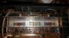
Hk560 Outputs.jpeg
 
If the bulb is that dim, that's OK. It's more or less what I'd expect.

Regarding the bias drifting, a starting point is to study the schematic. The bias network is usually a series of resistors, including the bias trimpot, biasing one transistor attached to the heatsink. The current flow on that resistor network regulates the idle current. A shorted capacitor or leaky capacitor could allow some current to flow by other paths.
 
Ok, I´ll try, my understanding of schematics however is very very limited, like identifying components.
Trying and am willing to learn but its been difficult to wrap my head around it, find myself in awe when reading AK members that really understands:bowdown:

But as a starting point, drawings make things a bit easier:
Any components of interest?
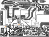
Left channel HK560 .png

So are these the capacitors that is of interest?

HK560 L CH Schematic.png
 
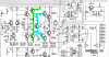
Bias network is around Q416. When Q416 conducts harder (adjusting VR404 or Q416 getting hotter attached to the heatsink), the bases of Q418 and Q420 are closer in voltage, lower voltage there, less bias current (pink line, what you are monitoring). Q416 pulls the voltage from Q418 and Q420 bases.

If Q416 is not reacting to heat, bias won't be stable. Q418 to Q242 will get hotter and hotter conducting more and more.

I'd start checking or replacing Q416, and checking the resistors in that network, comparing readings with the good channel. Check the voltage drop across that triple diode. Compare both channels. It should be around 2 volts, both channels similar reading. Don't risk the amp, you can measure from R442 to VR404, or so. Find a point electrically connected, with easy access. You can also monitor the voltage across R450 (100 ohm). Of course, check the soldering, broken traces, cold solder, solder bridges. Anything interfering that network will affect the balance.

hk-bias.png
 
Last edited:
Bias network is around Q416. When Q416 conducts harder (adjusting VR404 or Q416 getting hotter attached to the heatsink), the bases of Q418 and Q420 are closer in voltage, lower voltage there, less bias current (pink line, what you are monitoring). Q416 pulls the voltage from Q418 and Q420 bases.

If Q416 is not reacting to heat, bias won't be stable. Q418 to Q242 will get hotter and hotter conducting more and more.

I'd start checking or replacing Q416, and checking the resistors in that network, comparing readings with the good channel. Check the voltage drop across that triple diode. Compare both channels. It should be around 2 volts, both channels similar reading. Don't risk the amp, you can measure from R442 to VR404, or so. Find a point electrically connected, with easy access. You can also monitor the voltage across R450 (100 ohm). Of course, check the soldering, broken traces, cold solder, solder bridges. Anything interfering that network will affect the balance.

View attachment 2352303

Thank you very much for the elaborate explanation/drawing.
Barely understand it at the moment but this is great!
Will take the evening to study and try to understand.

May I just ask some very basic things to clarify?
I get confused of what readings should be done powered off or powered on so just to be safe:

1. Q416 (or transistors in general) check in Diode mode Powered off?
2. Resistors should be checked with Ohm-setting Powered off?
3. Voltage across R442 first then between R442 & VR404? Also R450 Powered on
 
Q416, and transistors in general, better to remove them from the circuit and test outside the circuit. You can also measure voltages at the transistor with the unit powered ON, that can tell you if the transistor is working as expected, but requires more experience and knowledge.

Resistors, without power, you need to measure the resistance , desoldering one end so you have an accurate reading without other components in parallel. They can be measured in circuit too, given that you have a good channel, comparing readings will show some difference between channels. If both channels measure the same, no problem there.

Voltage across resistors and across diodes, unit powered ON. I mean "from R442 to VR404" since they are directly connected to the diode, so it's the same to measure at the resistor ends connected to the diode, than putting the probes on the diode itself. Measure where you find easier to clip your probes without shorting anything else. Better to clip the probes before powering the unit and power on just to read the measurement, without poking inside the live amp.
 
Wow, That was more than I could wish for, very helpful! Much appreciated.

Will try to go over the components tomorrow, gotta study your previous post tonight.
 
Studied the drawings/schematic yesterday and it became a tiny bit clearer, interesting & fun, the functions are a bit difficult to grasp though,
Q416 pulls Voltage from Q418/Q420 when its colder and when its hot it conduct/releases voltage if I got it right?

Q416, and transistors in general, better to remove them from the circuit and test outside the circuit..
So I managed to get some readings but...
Unfortunately one of the heads to the screws on the bottom plate was very stubborn and broke so got to figure how to get it open before measuring Q416...

Anyhow here's the gathered readings from both channels in circuit (Left CH is the problematic):
Left CH / Right CH
R442 to VR404: 1.22V / R441 to VR403: 1.25V
R450: 1.22V / R449: 1.22V
R446: 681ohm (spec 680). / R445: 682ohm (spec 680)
R448: 683ohm (spec 680) / R447: 680ohm (spec 680)
R444: 9.98K ohm (spec 10K) / R443: 9.99K ohm (spec 10K)

Oh, there was two points on the VR404/403 and the one connected to the Diode was 1.22/1.25V the other measured 2.56V/2.57V
 
I don't see any relevant difference between channels.

Can you set the bias and monitor it for 15 minutes to see if it stabilizes at some point? Don't risk the amp. If it goes too high, power it off.

Keep in mind that the output transistors can hold several Ampere. A couple of mA won't damage them, even if the bias raises to 100 or 200mA.

Btw, Q416 , when hot, conducts more, pulling the voltage from Q418 Q420, so they have lower voltage at their bases. Imagine if you short Q418 base to Q420 base, voltage between those points would be zero. So, Q416 conducting more, less voltage at Q418 and Q420 bases. If Q416 is not conducting, higher voltage at q418 q420 bases, so more bias current.
 
Last edited:
Can you set the bias and monitor it for 15 minutes to see if it stabilizes at some point?
I could absolutely try that but first I might have found something:

Got the bottom plate off,
I know its not 100% accurate but when testing the caps in circuit with my ESR70, one cap C16 showed out of spec:
1000uf +50% -10% was 1770uf +77%, it is connected to Q2, it says it´s a voltage regulator, could this be the problem?
HK560 LCH.png
Regarding the Q416 function, Thank you, I got it backwards..will study your explanation/functions more.
 
As you mention, a capacitor reading in circuit is not accurate, you are measuring the whole circuit in parallel with that capacitor. Anyway it's a filter capacitor for a DC rail, I don't see it related to the bias circuit on the L channel.
 
I see, was hoping it was related.
Ok then I will try the recommended monitoring of Bias, will do this tomorrow and get back.
 
Hi again, Spent 1,5 hour monitoring the Bias (on DBT).
It slowly drifted up up, some short stable moments at 22,24 mV after 40 min.
after 1 hour it finally tries to regulate down around 26.8mV. Turned it off at 27.5mV.

Considering spec wants 33mV it would be quite an overshoot on full line?
 
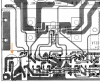
Oh, Also will just add this picture from the solder side,
not experienced in spotting bad/cold solder spots so if anyone sees any feel free to chime in.
HK 560 Solderside L.jpeg
 
HK 560 Solderside L.jpeg

Those points don't look very good in the picture, I'd double check with a mag glass. Or check resistance with your meter, from the component lead to the next component on the PCB trace.

Anyway it seems the amplifier is quite healthy, no shorts, bias stable, no DC offset. I'd set the bias a bit lower with the DBT (let's say 20mV where the manual specs 33mV), and check again, if it stays stable, I'd try it with full voltage, keeping one hand on the power switch just in case.
 
Very helpful, learning a lot here!
Some of those points didn't look too good with a mag glass, did you mean measure resistance only or with continuity mode?
They made continuity beep with dmm to next components though. But maybe should try to reheat the solder on those points anyway?

The thing is the trim pot is at its lowest so cannot adjust it down, its like its receiving too much current already from the beginning.
 
Back
Top Bottom