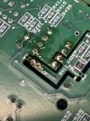
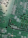
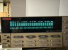
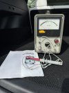
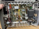
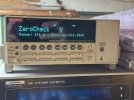
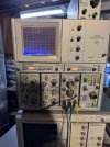
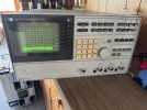
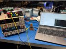
btw for anyone interested here is the rough scope of what I'm doing with automated test equipment/measuring rectifier performance in this Dynaco ST70 test bed:
it all started with this thread:
Max power test - JJ GZ34 vs Eico Gt Britain (Mullard?) GZ34 vs Solid State Rectifier Distortion performance in the same Dynaco ST-70
5AR4 Vacuum Tube Rectifier Evaluation Script — Rev 6
Instrument connections per rectifier_scan.xlsx.
K7001/K2001 scanning via trigger link cable.
HP 3562A dynamic signal analyzer added for speaker-terminal hum analysis.
═══════════════════════════════════════════════════════════════════════════════
INSTRUMENT / CONNECTION PLAN
═══════════════════════════════════════════════════════════════════════════════
HP 6813A AC Power Source / Analyzer (GPIB)
- Supplies 120 VAC / 60 Hz to the ST-70
- Measures: line Vrms, power factor (logged, not scanned)
Keithley 7001 Switch Mainframe (GPIB)
- Card slot 1: 7054 10-channel card
- Channels are closed one at a time; K2001 reads through the closed channel
Keithley 2001 7.5-digit DMM (GPIB) — reads all scanner channels
Ch 1 : VAC — Power transformer secondary pin 4 to ground
Ch 2 : VAC — Power transformer secondary pin 6 to ground
Ch 3 : VDC — Left OT primary current (HP 428B output, 3 V range → mA)
Ch 4 : VDC — Right OT primary current (HP 428B output, 3 V range → mA)
Ch 5 : VDC — Bias voltage, left channel
Ch 6 : VDC — Bias voltage, right channel
Ch 7 : VDC — B+ at 30 µF cap (first filter, from rectifier) + VAC ripple
Ch 8 : VDC — B+ after choke (20 µF) + VAC ripple
Ch 9 : VDC — B+ "A" rail to 7199 pentodes (20 µF) + VAC ripple
Ch 10: VDC — B+ "B" rail to 7199 triodes (20 µF) + VAC ripple
Note: Channels 7–10 are read twice — once in VDC mode, once in VAC mode —
to capture both the DC level and the superimposed ripple voltage.
HP 428B Clip-On DC Milliammeter
- Two units: one per output transformer primary center tap
- Output: scaled voltage on 3 V range (read via K7001/K2001 channels 3 & 4)
- Calibration factor set in HP428B_SCALE_MA_PER_V below
Stanford Research SR630 Thermocouple Scanner (GPIB)
- All channels: Type T thermocouples
Ch 1 : Ambient temperature
Ch 2 : Left output transformer temperature
Ch 3 : Power transformer temperature
Ch 4 : Right output transformer temperature
Tektronix TDS5054B Oscilloscope (GPIB)
CH1 : Tek P5210 differential probe
→ Rectifier pin 4 to pin 8 (anode A to cathode)
→ Forward voltage drop, half A; conduction angle
CH2 : Tek P5205 differential probe
→ Rectifier pin 6 to pin 8 (anode B to cathode)
→ Forward voltage drop, half B; conduction angle
CH3 : Tek TCP202 current probe (TekProbe BNC)
→ Output of rectifier pin 8 (DC load current)
HP 3562A Dynamic Signal Analyzer (GPIB address 5)
CH A : Left speaker terminal (across dummy load, direct connection)
CH B : Right speaker terminal (across dummy load, direct connection)
- Span : 0–200 Hz, 400 lines (0.5 Hz/line resolution)
- Window: Flat-top (±0.01 dB amplitude accuracy at 120 Hz)
- Mode : dual-channel FFT power spectrum
- Reports: amplitude at 120 Hz (dBV and Vrms), full spectrum saved,
L/R balance at 120 Hz, noise floor at 120 Hz bin
Connection note: dummy loads (8 Ω / ≥ 25 W) must be connected across
both speaker terminal pairs before powering the amplifier. The 3562A
connects directly across the dummy load terminals. Its input is rated
±25 V peak; auto-ranging is enabled to protect the front end.
═══════════════════════════════════════════════════════════════════════════════
MEASUREMENT STRATEGY
═══════════════════════════════════════════════════════════════════════════════
For each tube under test:
1. Warm up (600 s) with all output tubes installed at nominal bias.
2. No-load pass: bias at minimum.
- All 10 K2001 scanner channels (DC + ripple where applicable)
- SR630 temperatures (all 4 channels)
- Scope: forward drop waveforms (CH1, CH2), DC current (CH3)
- 3562A: 0–200 Hz FFT spectrum, CH A & CH B; extract 120 Hz amplitude
- 6813A: Vrms, power factor
3. Idle-load pass: output tubes at nominal idle bias, no signal.
- Same measurements as above.
4. Calculate:
- Ri = ΔV_B+ / ΔI_load (V from Ch7 DC, I from TCP202 on CH3)
- Forward voltage drop per half-wave (mean of CH1, CH2 measurements)
- Conduction angle per half-wave (duty-cycle measurement on CH1, CH2)
- OT primary currents (mA from HP428B via channels 3 & 4)
- Ripple attenuation through the LC filter (Ch7 ripple vs Ch8 ripple)
- 120 Hz hum at speaker terminals (dBV), L/R balance
5. Optional --conduction: narrow-timebase conduction angle analysis.
6. Log everything to CSV; save scope screenshots and 3562A spectra per
condition.