• The move to the new server is done. There are some software and database maintenance updates in process. This has us passing the hat around to help out. We appreciate any donations. Seriously, even a dollar helps. The payment page may be found here - https://www.audiokarma.org/support.html

Parts and Pieces: A True ARC Mystery

I think the AC panel would be much easier

I believe you're right. An AC panel wouldn't have so much stuff hidden under other stuff. That's one thing that the National Electric Code is good for- preventing that kind of confusing stack-ups of components. An electrician wouldn't touch something that convoluted. It's a special kind of talented tech, that can keep track of all these things running all over the place, at all sorts of angles, behind other things...

Regards,
Gordon.
 
Sometimes you take two steps forward only to then take one step backwards, or in this case, I almost ended up taking the board back out before I could even start wiring it. I guess had it come to that, that wouldn't have necessarily been a bad thing as I'd sure hate to have to take it out after it's all or even partially connected up.

Most ARC amps of a given time period are simply variations on a theme, which is true with most manufacturers; no reason to keep reinventing the wheel with each product, so given blocks of circuit design are regularly and routinely copied from one design to another. With that in mind, then consider:

Since about 1975, ARC started including a simple R/C network at the input jack to form a low pass filter for filtering out garbage HF transients. Early on, in amplifiers like the D-76A, this consisted of a 10K resistor connected in series with the signal presented at the input jack, followed by a 390 pF cap to ground. Assuming the output impedance of the preamp used is small, this produces a time constant of 3.9 µsec for a cut-off frequency of 40.81 kHz -- which is entirely reasonable for such a filter included in an amplifier intended for audio amplification.

Now fast forward to 1983 where the D115 has just been developed and is being produced. The HF garbage filter is still there, but has now taken on the form of a 3.92K series resistor, followed by a 100 pF cap to ground. Hummm. These components produce a time constant of just 0.392 µsec, for a cut-off frequency of just over 406 kHz. This always bugged me because this is RF territory, making the filter nearly worthless in stopping any transients a filter of this type and at this location in the circuit would be intending to stop. A check of both the original D115 and D115 MK II schematics showed that the same components were used in both. Even on the much better drawn schematics available at the ARC database site, the same component values are shown. Surely in all of this attention given to the schematic, any error in value would have been caught at some point. And, given the nature of this project in wanting to see, taste, and measure everything about this amp as ARC produced it, I let go of my concerns and continued moving forward. So, with multiple schematic corroborations and a drive to hear and measure the amps as they were produced, the filters were built into the input jack assemblies as indicated.

Now it's last night and I'm searching the net for a good pic of the underside of the amp with its bottom cover installed so as to copy the pattern of all the cooling slots in it for the new bottom cover being made (I never found one -- if anybody has one I'd be most grateful for a good pic of it), when I run across a schematic for the D70, which is the smaller sibling of the D115 by half, and developed/sold at the same time as the D115. In the D-70 -- which is virtually identical in design to the D115 minus a couple of power tubes in each channel -- the garbage filter is there, but the input series resistor is shown as a value of 39.2K, followed by a 100 pF cap to ground -- a combination that produces a virtually-the-same 3.92 µsec time constant as used in the earlier amplifiers, and a cut-off frequency of 40.60 kHz -- also insignificantly different from the earlier amplifiers as well. With the revised filter values however, the filtering effect is the same as with the earlier values used (i.e., as used in the D-76A, etc), but now the filter is also helping to significantly reduce the rather high input sensitivity of the design -- which was also a concern of mine with so much power on tap.

By all I know and understand then, it makes sense that the value of the input series resistor as shown on every D115 schematic I can find is wrong by a position of one decimal point -- an easy error to make I suppose on a schematic that is hand drawn by someone not necessarily intimate or involved with the actual design. With the ease of the potential type of schematic error made, the fact that a value of 3.92K simply makes no sense (while 39.2K does), and the fact that a virtually identical but half-power cousin is shown to use a value of 39.2K in the same filter as well, I have removed the input jack assemblies and changed the input series resistor to now be a value of 39K (hand picked to be within -0.25% of ARC's 39.2K value in each channel), which just make more sense. And thankfully, I did it (and was able to) before all the wiring became so dense as to not being able to remove them without undoing any wiring already done.

Of course, making such a change now puts the actual input impedance and (potentially as well) the input sensitivity at odds with the published specifications -- but input sensitivity and other factors like the stated amount of NFB employed are all over the map with this amplifier (depending on which "tentative" (ARC's term) specification sheet you're looking at), and they do not vary in any kind of rational interacting way between themselves either, so none of these things (other than the input impedance) will truly be known until the amplifier is actually put under the microscope. But either way, I feel good about changing the input series resistor to 39K for all the reasons cited, all the schematics notwithstanding.

So now that that little detail is addressed and settled, I can get back to the spaghetti.

Dave
 
That looks like it was one of the revisions between MK1 and MK2 in the D-70 anyway. That would explain the high frequency roll off of 60k for the MK1 and 30k for the MK2. It doesn’t look like they changed that in the D-115 and it also retains the same high frequency roll off of 60k.
 
And there ya go -- more ambiguities. In the D115 information however, there is absolutely zero information given relating specifically and technically to the frequency response of the unit. Such a specification is generally made by testing the amplifier with a consistent input level over the entire frequency range to be tested, and at a power output level of 1 watt (based on 1 kHz), so that the output transformer can't be a limiting factor that distorts the data.

What is specified for the D115 is the Power Bandwidth specification -- the frequency extremes at which the amplifier will still output 50% of its rated power. This of course is a far different specification than a specification of frequency response is, as in this case, it lays bare the limitations of the output transformer when its limits are met. Signal level required to achieve these power output end point is not a concern with this specification. In all the information I can find then, both versions of the D115 have a Power Bandwidth specification of 60 kHz on the high end as the -3db power loss point. This implies that the output transformers in at least the D115, likely remained the same over all versions. But any information on actual frequency response as this filter might impact? Nada.

Dave
 
Another distraction from the spaghetti, but this time, a much needed one: The AC Power Relay finally arrived, so I mounted it and connected it into the circuit, completing the AC Power section of the amplifier with the exception of installing the dual Current Limiters this unit uses. There is no specification given for them, so they will ultimately have to be determined on the basis of testing once the amplifier is otherwise 100% complete. Until that time however, a variac will serve as a soft start device to allow for powering up the various circuits as they are completed and then tested for proper operation. Having/needing the capability to do that makes completing the AC Power portion of the power supply a high priority, and ensures that the ultimate power up of the completed amplifier will be uneventful, if not boring.........

Dave
SAM_3144.JPG
 
Wow, That's snug!
Good catch on the filter. It would have slipped passed most of us (maybe everyone but you).
I am thinking the originals might've been built with the wrong filter as well. The factory just following the drawings given (filter just would have been useless). Food for thought.
 
Good progress for today: For the orientation of this pic, the left side power supply trunk is now complete on the power supply end of things. There's a lot going on in this trunk, with wiring for:

1. The AC power relay.
2. The AC power switch.
3. The AC power LED.
4. The Screen Grid fuse.
5. The Screen Grid power LED.
6. The Driver Regulator board.
7. The driver B+ for both channels.
8. The output tube plate B+ for the right channel.
9. The output tube ground connection for the right channel.
10. Heater power for the KT120 regulator pass tube.
11. Heater power for the four 6FQ7 tubes.

With the wiring for so many circuits addressed on the power supply end now (and many of those leads already terminated on the other end due to the pre-wiring of the board), it put a nice dent in the spaghetti mess shown earlier, making it easier to work on now as well. Overall then, today was the first time I felt like I was assembling a kit with this project, rather than attending to the seemingly never ending details that have absolutely dominated if not overloaded this project from the very start. But with the details virtually all addressed now, that work is really paying off in spades as the final assembly effort is going very smoothly -- knock on wood.

A few more connections to make, and then I will be able to start the process of connecting the power transformer secondary windings one at a time, and testing the circuit each powers along the way. Then connect another PT secondary winding and test that circuit, and so on. In this manner, by the time I get to a full power up, all the circuits will have been pretested to ensure there are no problems. The order will go as follows (all tubes installed except output tubes):

A. Bias supply test (controls set for max negative grid voltage).
B. DC heater power test.
C. AC heater power test.
D. Main B+ power supply test.
E. Screen grid power supply test.
F. Driver stage regulator test.
G. Input stage/cross-coupled regulator test.
H. Misc tests for heater bias, relay power, etc.
I. Test for correct (for the scenario) voltages at each output tube socket pin.

Once these circuits all pass full inspection, I will let the amplifier burn in for an hour or so as is. Then I'll power it down, install the output tubes (test pieces to begin with and then ultimately GE 6550A tubes), and test each circuit all over again. Once it's stabilized with all hands on deck, then the real fun begins! For now however, it's back to client work (with a service bulletin for Fisher 50A, 55A, and 200 amplifiers coming out of that work), and a peak at where this project currently stands:
SAM_3149.JPG

Dave
 
The wiring is all but finished now, with the exception of wiring the output transformers -- I just haven't had a need for them to be wired for the initial tests I've been making which include:

1. AC Heaters.
2. DC Heaters.
3. Bias Supply (> -40 vdc at pin 5 of each output tube socket).
4. Relay power.
5. AC power soft start and power switch circuit.

A single CL-90 serves perfectly at this point as a temporary current limiter since no output tubes are installed, and the B+ supplies are not operating. Also, there's only a 3A fuse installed for the line fuse at this point for the same reasons. The standard fuse is a 6.25 A Slo-Blo device. The design uses two current limiters in series -- I suspect that this will need to be two CL-80s when all is said and done, but testing will determine this for sure. A CL-80 is only a 3A device, but the current limiters are only in the circuit for literally about a second or so at turn on, after which the power relay removes them from the circuit. So, they don't have to be rated to handle the full rated current draw of the amplifier -- just the initial startup current.

Everything passed perfectly with flying colors with one exception. Sigh............

SAM_3150.JPG

It's way easier to swap the wiring than to swap the lamps (relatively speaking, but still hardly and easy change to make), which makes for a nice place to stop for the day.

Dave
 
After all that, if I flicked the switch and saw that I would walk away too. Maybe even have a drink, or two.
 
Yeah, I pre-wired the LEDs by attaching their connecting leads to them before installing them because you can't get to them to do that with the power transformer installed -- and particularly so because this power transformer is the international version with the extra primary winding. The leads for that winding appear right where the LEDs install so space is very tight in that area. The unit was (obviously) turned upside down when I installed them and I just installed them in the wrong holes. The wiring is corrected now so the proper LED lights for the function it indicates for.

Dave
 
OK, with the LED snafu resolved (exchanged the appropriate leads between the two diodes), I couldn't let the day end without knowing the status of the screen grid regulator since it was the last major circuit to be checked, and would also allow all the other circuits outlined in post #128 to be tested as well.

With both B+ power supplies connected (still no output tubes installed), a slow start with the variac and single CL-90 still in place brought everything up nice and easy, and after the big KT120 pass tube warmed up, the screen grid voltage was dead on the 312 vdc specified for the MK II amplifier. The KT120 just did it's thing as if it were the originally specified tube for that location. All the remaining circuits to test (outlined earlier) that are associated with (or powered by) the screen grid supply came in dead on the money as well -- principally, the output from the driver and input tube regulators, and the heater bias voltage.

Due to the design of the amplifier, the screen grid LED doesn't exactly follow the description of its operation as given in the manual. There it says that at power up, the AC Power indicator will quickly ramp up in brightness during the first second or so of operation, at which point the power relay will then pull in. Then about 10-30 seconds later, the screen grid LED will come on, indicating that the screen supply is operating.

Analysis of the circuit however had me concerned that the screen LED could not possibly operate that way, and it doesn't -- it does exactly as analysis of the circuit says it will do: At turn on, the screen grid LED comes on very quickly at almost the same time as the power indicator LED does. But after the input tubes heat (less than 10 seconds after turn on), those tubes then draw sufficient current that the screen grid LED then goes out. After a total time of about 20-22 seconds from turn on (when the KT120 warms up), the screen grid LED then comes back on and stays on from that point on. Not a big deal, but nether is it as described in the manual, either. In looking at every little detail as to how the amplifier actually performs versus how ARC says it should perform, that's difference #1.

As for the current limiters, because of the nearly 5000 µF that makes up the capacitance of the two B+ power supplies, these are currently sized at that of a CL-60. These are 5A devices, which again, don't need to pass the full maximum current that the amplifier can draw, but because the turn on surge is so strong due to just the capacitors alone (before the 8 output tubes are even installed), these need to be hefty devices. But hefty devices have very low current limiting resistance when cold, which limits how much surge the device can control. ARC therefore used two such current limiters in series: connected as such, the 5A rating is still the maximum current the two limiters can handle, but with two limiters, the cold resistance is doubled, which then helps to effectively control the otherwise huge turn on surge the amplifier would have. The current limiters may even need to be bumped down the the next level (6 Amps) when the output tubes are all installed, but for now, the CL-60s appear to do the job.

So that's about that. All that's left now is to wire the output transformers, and then install and bias the output tubes. A few pics follow.

It's starting to come together now!

Dave

BELOW: The current limiters are just tacked in at this point but otherwise, all that remains is to wire up the OPTs. The wires bent over each side of the amplifier are those coming from the two output terminal strips.
SAM_3151.JPG

BELOW: On the front panel, the proper fuse sizes are now installed, and the traditionally green LEDs that ARC used work as described earlier.
SAM_3152.JPG

BELOW: Up topside, everything is operating as it should -- even the DC balance for the driver stage has been adjusted as described in the manual. Once the OPTs are connected and the output tubes are installed and correctly biased, the amplifier should be ready to go.
SAM_3156.JPG

Dave
 
Sorry -- I haven't forgotten about this project by any means! It is a piece I work on in my spare time and certainly in between my diligent efforts with client pieces that also deserve attention (see the beginning of an update to my Fisher 55A thread I posted just this morning). They deserve a timely effort put in on their equipment, so I have to measure the time I can give to my personal projects when client pieces are here. Up to this point, I had just had a good run of time in either waiting on equipment to arrive, parts to arrive, an even how things fell together in my everyday living. I should be able to get back to it soon enough though. Until then, thanks for following along!

Dave
 
UPDATE:

With all due respect to Mary Shelly: IT'S ALIVE!!!! Well, the left channel is anyway....... And with little fanfair, too. It just powered up as if it had done so for years. The output tubes easily biased properly, as did the DC Balance settings of the input stage tubes. The AC Balance is has been left centered at this point. All voltages were either dead on, or so close as to be inconsequential.

The right channel only needs to have the two plate connections on the primary side of the OPT installed, and that's it. Well, almost that's it. Initial testing has put a spotlight on one issue that needs to be addressed (in both channels), and then the right channel will need to have it's output tubes installed, adjusted, and performance checked of course. But assuming nothing untoward comes from that effort, then: that's it.

I felt that with one channel completed, I ought to go ahead and do some initial testing, which at least would then allow for a complete check of the power supply under dynamic conditions. It would also highlight any issues specific to the left channel, or any issues that potentially might affect both channels. It would also let me know just where I am in the ball park with the channel I've got -- whether I'm in it, near it, or nowhere close. Because of the nature of this project and the resulting attention to details it has commanded (wrong chassis making for a 10 lb load in a 5 lb bucket and origin/original build/schematic issues), it ended up being a project that has been every bit as intense as a scratch new build of this amplifier would have been, and maybe even more so given the issues involved. With so much work having been completed then so that one channel could be operational, I thought it best to take stock of finding out just where things are. Obviously of course, there are no sonic observations to report as yet, and I wouldn't want to start those anyway until I was comfortable that the complete unit was operating as intended. So at this point it is very basic lab testing only, which has been enlightening to say the least. With that then, Here is the initial data I've gleaned from the left channel:

Test Conditions: Operating directly from my AC line of 120.5 vac. New generally matched Sylvania 6550 output tubes installed and biased to 52 mA each (ARC specifies 65 mA for each tube, but there's no reason to cook things that hot just yet). DC Balance set as specified. 4Ω load connected between the 4 and 16 Ohm terminals with 4Ω tap representing ground -- this because of ARC's floating Common terminal due to the partially cathode coupled output stage connection. Right channel small signal tubes installed and operating. This does not exactly replicate ARC's test conditions with regards to AC line voltage, output tube quiescent current draw, power supply current draw, and loading conditions, but is close enough for the general testing being done at this point.

Test Equipment: Heath IG-5218 Sine/Square generator, HP 3466A DVM, HP 400EL AC Voltmeter, and Tektronix 475A analog scope.

Modifications Installed:
1. Output tube screen stopper resistors have been changed from 47Ω 2W resistors, to 100Ω 0.25 watt resistors. This has no material effect on measured amplifier performance or its specifications, but provides for improved protection against the formation of any parasitic oscillations in the output stage, and improved circuit protection should an output tube decide to go off the ranch.

2. Output tube cathode sampling resistors have been changed from 1Ω 2W resistors, to 1Ω 0.5 watt resistors. Provides for improved protection under catastrophic output stage failure conditions. Both this change and that in #1 above still allow for the amplifier to develop full sustained rated power output for an indefinite period as might be required.

3. Screen grid regulator pass tube has been changed to a KT120 tube. Provides for original regulator operation as designed for 6550 pass tube, but with higher ratings to allow for full sustained power output in both channels without over dissipation of the pass tube (which clearly happens under those conditions with the 6550 tube originally specified). Because of this change, ZD16 in the cathode circuit of the 12AT7 error amplifier remains at the originally specified 12 volt designation, rather than updating this to the final 15 volt designation that final production units used at this location.

4. Output stage coupling and power supply HF decoupling caps upgraded in voltage rating only as needed so as not to have their ratings exceeded at any time when the amplifier is in operation.

5. Input garbage filter series resistor increased from schematic value by an order of 10X to match other ARC designs and considerations for this filter.

BELOW: Here we go!
SAM_3173.JPG


Power Output:
Maximum power output at 1 kHz at the onset of clipping, was exactly as specified at 110 watts RMS. Granted, this was only with one channel operating, where as the specification is with both channels operating. However, the output tube plate B+ supply only dropped 12 vdc from 0 to maximum power output (425 to 413 vdc), so the addition of the other channel will only have a minor effect if any on these results. Screen grid voltage is of course regulated, which is the most important design point regarding power output specifications.

More specifically, power output across the 20 Hz to 20 kHz audio band is also well met, with the test conditions/power supply comments above also applying here as well. In fact, the amplifier did so well, that other than for the limitations of my analog scope, it's virtually impossible to tell a 100 watt 1 kHz sine wave:
SAM_3169.JPG

From a 100 watt 20 Hz sine wave:
SAM_3170.JPG

From a 100 watt 20 kHz sine wave:
SAM_3171.JPG

This is impressive performance to say the least, where many an output transformer's limitations are on full display at the frequency extremes. Not so here. The transformers are fully capable of the power response specification as given by ARC. No distortion readings as yet, as that won't happen until I can move the unit over to my test bench, which has load resistors capable of the full sustained power output of which this amplifier is capable, and my HP 339A and Heath IM 5248 distortion analyzers. Suffice to say that the wave forms presented here indicate that the amplifier should have little trouble meeting these power output levels within the specified THD limit (<1% at 100 watts), and IMD limit (<0.1% at 1 db below 100 watts equivalent power output).


Frequency & Transient response:
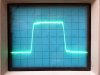
And here we hit a hiccup. A 10 kHz square wave into a normal resistive load produced the following results:
SAM_3167.JPG

What a heart breaker -- until I decided to bridge the input garbage filter series resistor with an appropriate external resistor to effectively bring it's value down to the schematic value of 3.92K. What a difference that makes!:
SAM_3168.JPG

To produce the specified 5 µsec rise time then (with a 10 kHz square wave), the schematic value of 3.92K is clearly the correct value (and also brings the unit much more in keeping with the specified Input Impedance and Input Sensitivity specifications as well).

While no frequency response information is specified for the D115 MK II, in measured response form, the two different resistor values look like this (Ref: 1 kHz = 0 db @ 1 Watt):
1. At 39.2K: @10kHz= -0.50db, @20kHz= -1.80db, @30kHz= -3.50db, @40kHz= -5.00db, @50kHz= -6.30db, @60kHz= -7.60db. It's pointless to go any further.

2. At 3.92K: @10kHz= -0.15db, @20kHz= -0.40db, @30kHz= -0.80db, @40kHz= -1.20db, @50kHz= -1.65 db, @60kHz= -2.15db, @70kHz= -2.60db, @80kHz= -3.10db.

COMMENT: So what does this say of (at least) the D76A and D70 amplifiers that are schematic specified to use the 39.2K series resistor value (the D76A uses different value components to achieve the same effective time constant)? Circuit wise, the D70 is a D115 with two output tubes ripped off from each channel. The input circuitry is equivalently identical. Ergo, if the effect of the resistor is as great as that shown above (which would be audible), it must similarly affect the D70 and D76A as well. Clearly then, there is no way that the D115 can meet its specified rise time, input impedance, or input sensitivity using a 39.2K input series resistor. So, the input jack assemblies will have to be removed again -- and before any listening tests can begin -- so that the original input series resistors can be reinstalled........again........ UGH!!


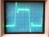
Transient Stability: Even with the input series resistor bridged down to 3.9K, the stability of the amplifier is nothing short of remarkable. With a cap only load and 10 kHz square wave input, a value of .25 µF across the 16Ω terminals produced about as much fuss as the amplifier would make, which was:
SAM_3172.JPG

Which is to say hardly any fuss at all.

Equally remarkable is the LF stability as well. When pulsed, the amplifier rises to the occasion of the pulse, and then the scope baseline falls right back to home -- no bounce, no muss, no fuss at all. And it does this whether there is a load on the amplifier or not!

Now, there is one caveat to the LF stability. If the pulse contains a strong DC component to it such as a pulsed square wave would represent, you can see the pulse momentarily deform the leading edge at the top of the square waveform as the input stages catches up to the new biasing conditions. There is no input coupling cap in the D115, and the output of it's first stage is direct coupled to its succeeding stages. So if the bias hiccups on the input stage, it hiccups on all the succeeding stages as well. Now any good preamp will have an output coupling cap which will prevent this event from occurring. Buuuutttt, the mentality of that day still lingers on with some to this day, so if your preamp's output coupling cap is so large that it can pass the DC component of a spike presented to it long enough to upset the D115's input stage bias, then that super hefty size coupling cap is likely doing you more harm than good, and could be yet another reason that some ARC output tube blow ups were so spectacular.......


Misc: Input sensitivity for 100 watts output came in at 0.61 vac rms, which is spot on for the MK II specifications, while hum and noise measured -90 db below 100 watts even with no bottom cover or tube cage cover installed.

As remarkable as this all was, there are things to pic at as well. Setting the DC Balance and output tube Bias is in fact the royal pain everybody as claimed it to be. The DC Balance pots are really too big in value, so that you sneeze in the next room, and it will impact the setting. Getting to the bias test points defies any sense of practicality, and then there's the heat. I'll go into these and other comments in more detail later, and there's still a whole bunch of tests to perform, but for now, suffice to say that this puppy appears to have all the goods it claims to.

Another pause while I redo the input jack assemblies and bring the right channel up to speed as time permits.

Dave

 
any thoughts on changing the balance pot to a smaller value and padding it out with fixed resistors to give a more reasonable adjustment range?
 
Wow, the performance at frequency extremes is nothing short of incredible! Did you check damping factor?
 
Wow, the performance at frequency extremes is nothing short of incredible! Did you check damping factor?
I do have a memory of D76 , it gave 80w across the audio range. I had no way of distortion measurement at the
time, but it sure met and exceeded spec. AR is a clear light in a world of grey knowledge.
 
Peter -- I'll give more thoughts on the ARC product once I'm finished with the testing and can get onto some listening tests. As for the D76, it was the D76A where the garbage filter first came into play with that amplifier -- it would be interesting if you knew which version of the amplifier it was.

Max -- ARC only specifies Output Regulation, which they indicate to be 0.5 db at the 16Ω tap between a loaded and unloaded condition. They indicate this to be a Damping Factor of ~ 17. This wasn't on my list of tests in the first go round, but it is with later tests to be done.

Gadget -- What with the board being so hard to work with, I'm thinking of just padding down the existing pots which should do the trick. That way I won't be trying to remove the existing pots and potentially chew up the board in the process.

Dave
 
Back
Top Bottom