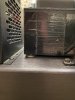
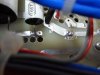
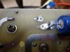
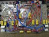
Planning is everything, even if it's just the AC power wiring. The IEC connector is designed to use push-on spade terminals -- except there's no room for them and the board when installed. So, as part of the chassis pre--wiring process, the leads to the connector are soldered to it, coming down to the terminals from running along the underside of the chassis deck. Up towards the front of the chassis, a hole in the side of the chassis provided there serves to mount a stud that firmly asfixes a lock washer ground lug to the chassis, to provide a secure chassis connection for the AC power ground lead. That's about the only way I know of to make a good ground connection to an anodized aluminum chassis that I know of, as the anodized surface doesn't conduct electricity, and of course you can't solder to it, so you need something that will cut through the anodized surface, which the lock washer does. The stud is long enough that after a jam nut is installed, a cable clamp is installed to hold the AC Power cord in place, and finally a T-Strip is installed to facilitate the AC power wiring, connections to the dual primary winding leads from the power transformer, the 30A soft start relay, and the dual thermistor leads.
Not shown, the AC Power mini-switch has also been removed to pre-wire it, since there is virtually no access to its terminals once installed (hidden by the power transformer leads). The LED indicator lamps will need to be pre-wired as well.
The output terminals also have to be pre-wired, and I can do that for the right channel terminals, but I'm still waiting on the material to come in to make the block that the terminals mount on for the left channel. So, once the pre-wiring I can do is done, then the project goes on hold until that material arrives, the blocks are then made, and the new board/with terminals is installed. After those terminals are pre-wired, then the board can be installed permanently, and the final wiring started. The final wiring will be quite a chore in and off itself as there are lots of leads already installed needing to interconnect with off board items, and more leads yet to be installed for the same purpose.
Sometimes on the schematics I draw and post, I am asked why I show the core of the OPT grounded. I do this because #1 it is by virtue of its mounting and #2, because grounding the core represents best practice shielding wise. So..... that's all out the window with this amplifier. The OPTs are both mounted on insulated washers, and secured by hardware that is insulated from the chassis as well. There is infinite resistance between the stack bolts and the chassis, or the lams, cover, and chassis. Now this should be interesting........... On the other hand, the power transformer (which has no bottom end bell) has the bottom most lam mounted directly against the top of the chassis deck, and on the underside, a fiber washer is placed first, then a steel washer, and finally a nut on each of the four mounting studs. Measurement between the stack bolts and chassis indicates a couple of Ohms resistance. The OPT mounting appears to be what it is, what it is, what is is. But I'm really questioning if this is standard power transformer mounting practice by ARC. I would think they would at least have stack bolt tightening nuts screwed onto the transformer mounting studs first before the transformer is set into the chassis, providing a space that is the thickness of that nut between the bottom most lam, and the top of the chassis deck (this is how the OPTs are installed). On the other hand, doing so means that the power transformer will sit higher than the OPTs (by the thickness of the extra nut), where as currently, the top of all three transformers represent the same height from the chassis deck as currently mounted. If there's anyone with a similar period ARC product (it doesn't have to be a D115) that could take a look and see if this is how their power transformer is mount and report back, it would be greatly appreciated!!
Dave

The apparent scratches aren't scratches at all and easily rub off, being what appears to be a surface residue from the anodizing process.......