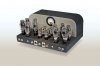
B+ to all small signal tubes is regulated, as is output tube screen and control grid voltage. DC heater voltage to the phase inverter and 1st AF Amplifier stages is also regulated. The only power sources that are not regulated in the design are the AC heater voltage sources (for all 6550s and 6FQ7 tubes), and the plate B+ for the output stage.
When removing 4 of the output tubes, the voltage to the AC powered heaters will likely increase somewhat, so it will be something I'll have to check -- on top of checking the general AC heater voltage levels to check how appropriate the primary windings are for today's line voltage levels anyway. The schematic indicates the unit can operate properly from a line voltage range of 105 vac to 130 vac when the 120 volt tap is connected. A tap is also provided for 100 vac operation as well. But this is all based on the single primary transformer shown on the schematic. The transformer in my unit however is a dual primary type, with each (presumably) 120 volt winding also having (presumably) a 100 volt tap as well. I won't know anymore until I can get the unit actually powered up with all tubes installed.
As for the effect of removing 2 output tubes in each channel on the OPT, the effect is actually quite opposite that suggested, where the use of what then amounts to an effectively well oversized OPT extends the LF power response of the amplifier, and also increases transformer efficiency due to the lower maximum power level the transformer is dealing with. As a result, power output from such a move is typically more than half the power output that four tubes produce. If anything, the biggest concern will be to watch what effect removing two tubes has on the HF end of the power response curve. Here, the winding capacitance of a transformer designed to handle basically twice the power actually generated can potentially load down the two tubes left operating, so that the HF end of the power response curve can be reduced. Again, this will have to be checked once the unit is actually powered up, and these tests can be run.
OK, a few pics to show current status:
Below: Just as ARC had to do, the chassis has now been relieved so as to give proper clearance between the phase inverter tube, and the rear side chassis cutout for the board.
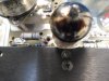
Below: The clearance between the adjusting screw of the left electrolytic cap mounting ring and the rear side of the front lip of the cutout in the chassis for the circuit board is very tight -- but works. No sparks fly if they touch, but it could create a ground loop since the chassis is only grounded to the board via the board mounting screw nearest the phase inverter tube (shown above). Board positioning was critical, but has been successfully implemented.

Below: A very important success point in the project: The circuit board is now fully mounted in place by all 16 board mounting screws, providing this pic, as well as the two previous pics. It's actually starting to look like something! Note too that a black terminal has now been installed to identify the Com terminal in the Right Channel's upgraded output terminals previously installed before arriving here. With this board install, notes have also been taken as to the pre-wiring that needs to be done before it is permanently installed. Some leads need to be attached to the board, while others to chassis mount components before the board's final installation. Details, details.
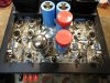
I am on the fence about whether to counter-sink the new holes for the board mounting screws as the original holes were, as the new holes run into the old ones, and I'm afraid the counter-sink might rip up the elongated holes as they currently exist to actually make it look less acceptable than it does now. Also, any cuts made to the chassis cut below the anodizing effect, causing an appearance which stands in sharp contrast to the anodized look of the original chassis stamping anywhere that contrast could be seen. As is with the screws used, the appearance is that the chassis is one that can accommodate two different size boards, with the holes for the larger size board simply being used in this case. Actually, that's all quite true now, making me tempted to leave well enough alone, or possibly find some appropriate anodized fender type washers to cover the original holes. That would require longer mounting screws, as the ones used are perfectly suited length wise as is, but probably not long enough if washers are installed. Such washers might also actually draw more attention to the unused holes as well, so again, might be best to leave well enough alone. Not being counter sunk, they do interfere with the cage setting flush on the top of the chassis. But with the low profile board mounting screws used, the cage could be mounted on 1/8th inch (or shorter) spacers, and call it a day. You'd never really know unless you knew to look for it, and it would allow more cooling air to enter the cage as well. More stuff to ponder.
Dave