• The move to the new server is done. There are some software and database maintenance updates in process. This has us passing the hat around to help out. We appreciate any donations. Seriously, even a dollar helps. The payment page may be found here - https://www.audiokarma.org/support.html

Parts and Pieces: A True ARC Mystery

Oh commenting of the caps, its sort of a mystery to me that ARC would use the underated caps in the first place:idea:

This type of "bean counter engineering" is common. In automotive technology. If you can save a few cents per part, but you used 4 million of those parts, you just made the company substantially more dough. You only have to stand behind the ones which actually break and do so within the waranty period.
Jump on mouser, and find a value of cap, start at 50 volts and note the cost. Now price them in 100v, 200v 350v,450v and 600v, you will have your answer.
Its a lot more common than people like to admitt. Great thing about having a real tech work on gear, is they can find these pitfalls and correct them for you.

Everything is a kit.
That mentality has changed the way i think.
Anything you buy at any store had compromises made in order to bring it to market at a low price point, or to increase magins for management. If we apply ourselves we can usually make things better, and bring them to a higher standard than the factory could.
Dave is an inspiration to all of us kit builders.
 
This type of "bean counter engineering" is common. In automotive technology. If you can save a few cents per part, but you used 4 million of those parts, you just made the company substantially more dough. You only have to stand behind the ones which actually break and do so within the waranty period.
Jump on mouser, and find a value of cap, start at 50 volts and note the cost. Now price them in 100v, 200v 350v,450v and 600v, you will have your answer.
Its a lot more common than people like to admitt. Great thing about having a real tech work on gear, is they can find these pitfalls and correct them for you.

Everything is a kit.
That mentality has changed the way i think.
Anything you buy at any store had compromises made in order to bring it to market at a low price point, or to increase magins for management. If we apply ourselves we can usually make things better, and bring them to a higher standard than the factory could.
Dave is an inspiration to all of us kit builders.

I get that mentality. My thought was a car company selling 10s/100s of thousands of units has a real if questionable + side and I think less likely in upscale vehicles.
These are high end low volume pieces with a reputation that would follow them more closely.
 
Do mind if i ask?
It seems there's a fair amount of dressed wiring (routed and ty wrapped).
Is this because of the nature or what it is? (An enigma of sorts?) Or would a production unit have that as well?
Oh commenting of the caps, its sort of a mystery to me that ARC would use the underated caps in the first place:idea:

I think in this case- it may have been a classic case of pride before a fall.

In the 1970s and 1980s- many of the new, fancy, "boutique" high-end caps, were only available in up to 400v rating- maybe 450v, if you were lucky. So, to have the "street cred" of having the "extra special" caps- a bit of a blind eye was turned to things such as peak turn-on surge voltage, what happens if the amp is plugged into an AC circuit with higher-than-normal voltage, and such. ARC certainly wasn't the only ones that did this- they absolutely pale in comparison to the amount of "voltage limit abuse" that occurred in Counterpoint amps and preamps in this era.

That is, in essence, one of the major reasons why tube gear got a reputation of being "temperamental", "dangerous" and "unreliable" in the 1980s- in essence, why tube amps of this era, not infrequently went up in showers of sparks, pops, bangs, and fire. However, once common sense was able to take the day again, and things started to more jibe with reality in terms of voltage limits (getting boutique cap manufacturers to build caps with higher voltage limits helped a lot!), in the 1990s, most tube amp manufacturers saw the errors of their vanity, and took appropriate action to correct these cap working voltage inadequacies. When using caps, of actual sufficient voltage rating, returned to being standard practice- things started to calm down and amps became reliable and rugged again- like they had generally been, back in the heyday of tube audio, in the 1950s through the early 1970s.

This is the main reason why I do NOT own any 1980s tube amps... they self-destruct to such an extent, that, like what Dave has gone through above- they are dauntingly difficult to get working, reliably. And Dave was actually lucky here- I've seen more than a few ARC and other tube amps of this era, where the circuit board was so cooked, that the through-the-board circuit leakage made it impossible to get the amp to run stably. I remember one Audio Research D75 in particular, that went through the hands of a half-dozen owners and technicians- each trying to get it to work without runaways and noise. Each of them finally came to the realization that the circuit board itself, was too far gone, from heat and component failure damage- that there was NEVER going to be a way to get it working without a complete set of new boards. And nobody was willing to pay the extraordinarily high cost of having ARC do that (it was like 70% of the cost of a comparable new amp, back then!), so the amp just went around and around, like the proverbial hot potato, for quite a few years...

Regards,
Gordon.

 
I think in this case- it may have been a classic case of pride before a fall.

In the 1970s and 1980s- many of the new, fancy, "boutique" high-end caps, were only available in up to 400v rating- maybe 450v, if you were lucky. So, to have the "street cred" of having the "extra special" caps- a bit of a blind eye was turned to things such as peak turn-on surge voltage, what happens if the amp is plugged into an AC circuit with higher-than-normal voltage, and such. ARC certainly wasn't the only ones that did this- they absolutely pale in comparison to the amount of "voltage limit abuse" that occurred in Counterpoint amps and preamps in this era.

That is, in essence, one of the major reasons why tube gear got a reputation of being "temperamental", "dangerous" and "unreliable" in the 1980s- in essence, why tube amps of this era, not infrequently went up in showers of sparks, pops, bangs, and fire. However, once common sense was able to take the day again, and things started to more jibe with reality in terms of voltage limits (getting boutique cap manufacturers to build caps with higher voltage limits helped a lot!), in the 1990s, most tube amp manufacturers saw the errors of their vanity, and took appropriate action to correct these cap working voltage inadequacies. When using caps, of actual sufficient voltage rating, returned to being standard practice- things started to calm down and amps became reliable and rugged again- like they had generally been, back in the heyday of tube audio, in the 1950s through the early 1970s.

This is the main reason why I do NOT own any 1980s tube amps... they self-destruct to such an extent, that, like what Dave has gone through above- they are dauntingly difficult to get working, reliably. And Dave was actually lucky here- I've seen more than a few ARC and other tube amps of this era, where the circuit board was so cooked, that the through-the-board circuit leakage made it impossible to get the amp to run stably. I remember one Audio Research D75 in particular, that went through the hands of a half-dozen owners and technicians- each trying to get it to work without runaways and noise. Each of them finally came to the realization that the circuit board itself, was too far gone, from heat and component failure damage- that there was NEVER going to be a way to get it working without a complete set of new boards. And nobody was willing to pay the extraordinarily high cost of having ARC do that (it was like 70% of the cost of a comparable new amp, back then!), so the amp just went around and around, like the proverbial hot potato, for quite a few years...

Regards,
Gordon.

Thanks. Thats an interesting angle I hadn't considered which gives conversation context
 
Something like that I'd be tempted to gut and build something completely different in the box with those transformers. Sounds like thats about all there truly was to work with.
 
Absolutely interesting context Gordon.

From a design standpoint, there is really no reason for the output tubes in this design to go Chernobyl except for damage being done to the output tube couplers everytime the unit is turned on:

1. For 6550 tubes, the plate voltage is hardly excessive at 430 vdc.
2. For 6550 tubes, the screen voltage is hardly excessive at 312 vdc.
3. For 6550 tubes, the plate dissipation is hardly excessive at: .065 cath mA - 3 screen mA = .062 plate mA X 430 vdc = 26.7 watts, or 63.6% of the Design Maximum Pd rating.
4. 1Ω 2 watt plate stoppers are used at each output tube. (these could really use just 0.5 watt rated devices)
5. 47Ω (now 100Ω) screen stoppers are used at each output tube; originally 2 watt devices, they are now 0.25 watt devices. (rating still allows for continuous maximum power output of any time duration)
6. 1KΩ control grid stoppers are used at each tube.
7. 1Ω cathode current sampling resistors are used at each tube; originally 2 watt devices, they are now 0.5 watt devices. (rating still allows for continuous maximum power output of any time duration)
8. The output tube sockets are caliber pieces that grip the tube pins very well.

So the operating conditions hardly encourage an output tube meltdown scenario in the amplifier, and stoppers resistors are included for each output tube element as well. The screen and cathode stoppers have been downsized to more appropriately rated wattage devices for the design, and each tube can be individually biased to the correct current draw. With the tube cage removed, ventilation is very adequate.
About the only thing left then addressing the voltage rating of the coupling caps. The ones now installed are quality pieces that have ample reserve rating, so they should no longer be a factor, in any event.

The real drive for me behind getting this unit to work properly as designed, is to see just how well it actually measures up to its sonic reputation, and published specifications. The specifications between the original D115 and the MK II version changed, but not in a way that would be consistent with the details of all the changes made. As such, it was hardly uncommon for vintage manufacturers -- when a design changed -- to either not update the original specifications, or only update the major points, leaving everything else still representative of the original model. So, that can all get sussed out. To my knowledge, nobody has ever put one of these beasts through its paces to see what it is really capable of. I don't know if the price of admission for such an expensive amplifier ($3000 in 1983) also buys an understanding that specifications are always or automatically met or what, but I hope to find out. I'll share all of that once this puppy gets up and running........

Dave
 
Dave- would it be possible to briefly explain the self healing nature of film capacitors? Not something I’ve heard about before but I’d certainly be interested in learning exactly how that occurs.
 
Here's a really good explanation of capacitor self-healing:

https://passive-components.eu/the-self-healing-characteristics-of-metallized-film-capacitors/

It describes the mechanisms, the limitations, and the downsides of the "healing" process.

The problem that we see in running the caps so close to, or over, rated voltage- is that it increases the healing energy to the point, where by vaporizing one shorted area- the spike in current causes ANOTHER area to short and fail. This leads to the described "avalanche failure"- which, hopefully, will result in just a cap blown to an open circuit- but sometimes, there's enough damage that occurs at one time, so that the cap becomes an effective short circuit- it can't clear itself of all the simultaneous shorts, and passes high-voltage DC to places it doesn't belong. This is what has the potential of blowing up other parts of the amp, when this happens.

Regards,
Gordon.
 
Here's a really good explanation of capacitor self-healing:

https://passive-components.eu/the-self-healing-characteristics-of-metallized-film-capacitors/

It describes the mechanisms, the limitations, and the downsides of the "healing" process.

The problem that we see in running the caps so close to, or over, rated voltage- is that it increases the healing energy to the point, where by vaporizing one shorted area- the spike in current causes ANOTHER area to short and fail. This leads to the described "avalanche failure"- which, hopefully, will result in just a cap blown to an open circuit- but sometimes, there's enough damage that occurs at one time, so that the cap becomes an effective short circuit- it can't clear itself of all the simultaneous shorts, and passes high-voltage DC to places it doesn't belong. This is what has the potential of blowing up other parts of the amp, when this happens.

Regards,
Gordon.
Excellent thanks Gordon!
 
Me too! But right now, I am absolutely dead in the water until the power relay and output terminal board material show up. Until then there is literally nothing I can do except wait, as everything except those things is done. I can't install the main board because the remaining output terminal board can't be installed while the board is installed. So, I just wait. So near, yet so far. But I've come this far, and am determined to see it through, so the minute anything arrives, I'll update the thread accordingly. The terminal board material is literally on a slow boat from China, and I've got the post office looking into why tracking shows the power relay bouncing back and forth a number of times between Toledo and Detroit -- both of which are way North of GA!

Dave
 
Well the slow boat must have hit some trade winds as the piece of 4 mm thick black plexiglass needed to make the left channel speaker terminal strip arrived sooner than expected. So the terminal strip has now been made (it is a two piece affair with one piece of plexiglass on the outside, and one on the inside of the chassis) and installed. Tomorrow I will pre-wire the strip (can't get to the back side of it once the board is installed), and then the main board can finally be permanently installed. Once that's done, then the maze of underside board wires can start to be routed and connected where they belong, and then tie wrapped in place like ARC did . Still waiting on the 30A power relay to arrive, but at least I can continue on now in the meantime. Of the remaining work to be done, installing the power relay is by far the easiest of all.

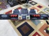
As for the back panel itself, labeling issues include the fact that there is obviously no model number silk screened onto the left side of the chassis (above the serial number), the input jack description is completely wrong (they are now unbalanced inputs of ~ 72K input impedance), and the full power AC current consumption of the amplifier is 1000 watts. Buzz is suggesting that to really make the rear panel correct, a new rear panel should be fabricated to fit over the existing one, to at least allow the correct information to be silk screened onto it. It would also eliminate the need for the raised output strip terminal mounting blocks, and the input jack adapter mounting plates I made. Something to ponder. Still, the existing rear panel is properly functional now in terms of the needs of the amplifier, and as is, likely projects an accurate look as to the original intention of the build: That being a D115 prototype amplifier (made out of workable parts and pieces that were on hand in the ARC labs), partially assembled for the ultimate purpose of developing a balanced input version of the amplifier. A slight adjustment was made to those plans when it arrived here, allowing the amplifier to finally reach a workable operating conclusion at least some 20 years later........

Dave

SAM_3140.JPG
 
One small suggestion: those bits of PC board which the RCA jacks are mounted on would likely look better if mounted on the inside of the chassis rather than the outside.

I'm looking forward to reading the conclusion of this thread, especially measurements.
 
Well the slow boat must have hit some trade winds as the piece of 4 mm thick black plexiglass needed to make the left channel speaker terminal strip arrived sooner than expected. So the terminal strip has now been made (it is a two piece affair with one piece of plexiglass on the outside, and one on the inside of the chassis) and installed. Tomorrow I will pre-wire the strip (can't get to the back side of it once the board is installed), and then the main board can finally be permanently installed. Once that's done, then the maze of underside board wires can start to be routed and connected where they belong, and then tie wrapped in place like ARC did . Still waiting on the 30A power relay to arrive, but at least I can continue on now in the meantime. Of the remaining work to be done, installing the power relay is by far the easiest of all.

As for the back panel itself, labeling issues include the fact that there is obviously no model number silk screened onto the left side of the chassis (above the serial number), the input jack description is completely wrong (they are now unbalanced inputs of ~ 72K input impedance), and the full power AC current consumption of the amplifier is 1000 watts. Buzz is suggesting that to really make the rear panel correct, a new rear panel should be fabricated to fit over the existing one, to at least allow the correct information to be silk screened onto it. It would also eliminate the need for the raised output strip terminal mounting blocks, and the input jack adapter mounting plates I made. Something to ponder. Still, the existing rear panel is properly functional now in terms of the needs of the amplifier, and as is, likely projects an accurate look as to the original intention of the build: That being a D115 prototype amplifier (made out of workable parts and pieces that were on hand in the ARC labs), partially assembled for the ultimate purpose of developing a balanced input version of the amplifier. A slight adjustment was made to those plans when it arrived here, allowing the amplifier to finally reach a workable operating conclusion at least some 20 years later........

Dave

View attachment 1988352

It looks great, Dave. Question: Have you ever worked with Delrin? Eminently machinable and great dialectric properties. Available in bars and sheets in black and white, in a variety of thicknesses, from McMaster-Carr. I use it for top plates, inserts, sub-chassis, what have you. Reduces resonance in tube circuits, etc.
 
Honestly ,
I think the back panel is fine.
Its clean , functional, (clearly an RCA isn't balanced), the 700w label doesn't trouble me at all).
At the end of the day, once hooked up you'll never see any of it.
From what its history is, id call this portion of the process an unqualified success :thumbsup:
 
Thanks for the comments -- all are sincerely appreciated:

Max -- Agreed. Except that things are soooo tight inside the chassis that I couldn't afford to lose the space between the back of the jack and the board, created by mounting the plate on the outside of the chassis. Being a V70 chassis rather than a real D115 chassis, it loses 3/4th of an inch in front to back depth versus that of a real D115 chassis, so the adapter plates ended up being mounted on the outside of the chassis by default. Maybe some paint might help their appearance though. Once finished and verified to be working properly, I will definitely put this sucker through a complete battery of tests (lab and listening room), and report back.

Zack -- No I have not, and thank-you for the suggestion. When it comes to matters like best materials to use for the details of physical construction, I am truly completely ignorant (other than for obvious things like the use of nonmagnetic materials, etc). I looked at the one output terminal block that had previously been installed, assumed it was bakelite, and went looking for it on the web. When I saw the price and quantities I had to purchase for the couple of small pieces I needed, I was really surprised. Also disappointed that I basically had to go off shore to get anything workable in the small amount that I needed. In the end, the black plexiglass I got may not be the same exact material as was used for the original terminal block (in fact, I'm rather sure it's not), but ultimately serves the purpose well enough, and from an appearance standpoint, you'd never even realize the difference in materials unless it was pointed out to you -- and this for a rear panel that is already well modified from its original design. Remember too that the IEC electrical connector is also a modification to the rear panel, as ARC was not using those connectors at the time the D115 was being produced. Finally, there is the usual camera distortion in that pic, making the chassis and things on it appear to be either bowed or mounted crooked -- which is not the case in actual fact. Everything is aligned and straight as it should be.

NJ -- That is the feeling I tend to have as well. Physically, this amplifier can never be an authentic D115 even if I had a perfect copy of a D115 chassis made, because the copy would still be just that -- a copy, and not an authentic ARC piece. Even electrically, while it's 99.999999% true to to the MK II design (I did up the value of the original 47Ω output tube screen stopper resistors to 100Ω), the parts I used to finish the board out weren't the exact same pieces as ARC used, but hand picked quality pieces of similar construction that ultimately should prove to be insignificant in terms of the final results. So it's close, but no cigar, and trying to dress it up further to get the cigar still ultimately leaves you with no cigar, because it can never warrant one. Heck, the sole fact that I (basically) built the thing disqualifies the cigar, as it ultimately was not produced by ARC. But, it is chocked full of all the ARC goodies that make up the heart and soul of a real D115, which frankly is good enough for me. So, it is, what it is, and interesting enough at that. The front panel gives a clean representation as to intent and origin, while everything behind it has been done to a level that hopefully WZJ would still be proud of.

Dave
 
Delrin does machine very nicely. I had to make an adapter flange for something at work and it cuts nicely, if a bit loudly on the lathe. Not sure if it was just the tool geometry I was using or what but it made a bit of a screaming noise when I had things cutting nicely.
 
Progress --

Below: The rear panel is finally finished with the pre-wiring of the left channel output terminal strip installed yesterday. The wiring from both terminal strips is visible on the top side of the board (when installed), but must be connected so that it can be pushed up against the inside of the rear panel (to give allowance for the board when it is installed), and then routed along the underside of the board to its various connecting points near the front of the chassis.
SAM_3141.JPG

Below: Finally, the board is permanently installed now, firmly secured at all of its mounting points, with adequate clearance for all the rear panel connections, as well as for the front most large electrolytic cap mount rings, and the rear most (phase inverter) tube. All of the large power supply caps are also fully installed now along with their cover caps, and have previously been checked to insure their form is in tact. The positioning of the board within the board cutout also allows for the tube cage to be installed if desired using the mounting holes for that purpose. The height of the KT120 regulator tube (a necessary upgrade from the stock 6550 called for in that location) is exactly equal to that of the four main electrolytic caps.
SAM_3142.JPG

Below: Other than installing the AC power relay (still waiting to arrive), all that remains now is connecting all of this up, and routing it as neatly as possible so as to be able to make sense of it all. Long ago, I lost track of all the time and effort involved to get this project to this point, but it's finally here, so there actually seems to be some light at the end of the tunnel now.
SAM_3143.JPG

More as it happens but this will take a while, as besides all the wiring above, there's still plenty of wiring to install that isn't visible even here (it wasn't part of the pre-wiring where connections had to be made that would otherwise not be accessible with the board or large electrolytic caps installed. Geez, in some ways, I feel like I'm wiring an AC power breaker panel!

Dave
 
Thanks for the comments -- all are sincerely appreciated:

Max -- Agreed. Except that things are soooo tight inside the chassis that I couldn't afford to lose the space between the back of the jack and the board, created by mounting the plate on the outside of the chassis. Being a V70 chassis rather than a real D115 chassis, it loses 3/4th of an inch in front to back depth versus that of a real D115 chassis, so the adapter plates ended up being mounted on the outside of the chassis by default. Maybe some paint might help their appearance though. Once finished and verified to be working properly, I will definitely put this sucker through a complete battery of tests (lab and listening room), and report back.

Zack -- No I have not, and thank-you for the suggestion. When it comes to matters like best materials to use for the details of physical construction, I am truly completely ignorant (other than for obvious things like the use of nonmagnetic materials, etc). I looked at the one output terminal block that had previously been installed, assumed it was bakelite, and went looking for it on the web. When I saw the price and quantities I had to purchase for the couple of small pieces I needed, I was really surprised. Also disappointed that I basically had to go off shore to get anything workable in the small amount that I needed. In the end, the black plexiglass I got may not be the same exact material as was used for the original terminal block (in fact, I'm rather sure it's not), but ultimately serves the purpose well enough, and from an appearance standpoint, you'd never even realize the difference in materials unless it was pointed out to you -- and this for a rear panel that is already well modified from its original design. Remember too that the IEC electrical connector is also a modification to the rear panel, as ARC was not using those connectors at the time the D115 was being produced. Finally, there is the usual camera distortion in that pic, making the chassis and things on it appear to be either bowed or mounted crooked -- which is not the case in actual fact. Everything is aligned and straight as it should be.

NJ -- That is the feeling I tend to have as well. Physically, this amplifier can never be an authentic D115 even if I had a perfect copy of a D115 chassis made, because the copy would still be just that -- a copy, and not an authentic ARC piece. Even electrically, while it's 99.999999% true to to the MK II design (I did up the value of the original 47Ω output tube screen stopper resistors to 100Ω), the parts I used to finish the board out weren't the exact same pieces as ARC used, but hand picked quality pieces of similar construction that ultimately should prove to be insignificant in terms of the final results. So it's close, but no cigar, and trying to dress it up further to get the cigar still ultimately leaves you with no cigar, because it can never warrant one. Heck, the sole fact that I (basically) built the thing disqualifies the cigar, as it ultimately was not produced by ARC. But, it is chocked full of all the ARC goodies that make up the heart and soul of a real D115, which frankly is good enough for me. So, it is, what it is, and interesting enough at that. The front panel gives a clean representation as to intent and origin, while everything behind it has been done to a level that hopefully WZJ would still be proud of.

Dave

I call this the ARC by dcgillespie amp. Part ARC/ part Gillespie. The best of both.
 
Back
Top Bottom