…you have also referred to replacing lots of (or all?) capacitors.
Firstly, thank you for such a thorough and well advised reply. I sincerely appreciate it.
On the electrolytic capacitors. As I understand it, replacing old electrolytic is good practice only because of their age. I do understand that recapping is not repairing. Every electrolytic capacitor that has been desoldered was laid down on a sheet of paper, the location where came from on the board is written next to it a photograph is taken. I also took care to measure their values out of circuit, nearly all of them are in spec. What I don't have is an ESR meter but I plan to purchase Bob Parker's B2ESR from
https://evbesrmeter.pt. Only two caps were no good, one had the 'can' blown straight out and lying around on the PCB, the leads still soldered in and lots of little bits of silky like paper about. The other was bulging. Other than those two, my multimeter reported back good values for those that had been removed and there was no sign of bulging or leaking. I was actually amazed because on vintage computers caps this old will have already leaked.
If ESR and Farad values are good should I solder them caps back in?
Doing shot-gun (en masse) component replacement can easily create new problems.
I do agree. I hope I justified my approach when it came to electrolytic capacitors above but please advise me.
On resistors, I had to measure them all, one by one. I am documenting every action, it has taken me days just to do meter the values for resistors. I found some to be questionable in terms of actual values versus documented values. Now, I do understand that documentation (service manual) may have defects so I am being cautious about it. Here is how I am going about this, one by one, I am carefully desoldering one of the resistor leads out of circuit and measuring anew. I have already found that this method revealed what I had written down as a potentially bad resistor was actually good, which leads me to believe that another component (probably in series I don't know) was skewing results. In summary, only resistors whose values didn't match the documentation are being remeasured with one lead out of circuit. If it is good, I will update my notes and it gets soldered back in.
Don't consider replacing all capacitors or every resistor that shows some signs of prior heating.
Someone in this thread mentioned that the discoloration (PCB substrate having isolated areas that are darker - a sign of overheating) is a sign of overheating but that it likely didn't happen at once, that it happened over time. I tend to agree. As a result, I will follow your advice, it sounds reasonable. (I guess I should solder back those caps that measure nicely - will order the ESR meter soon)
As for the empty resistor locations: one important thing for you to attempt to determine is whether someone else has ever done any work in this amp. If so, the picture becomes more complicated.
To be clear, I did buy this amp used several years ago and it did work perfectly. I used it two or three times after purchase then I flew back to Ireland where I was working at the time. Half a year later, I return from Ireland, power up the amp and poof, a little bit of yellowish smoke came out the back of the unit. I don't recall hearing any noise coming from inside the amp. I turned it off as quickly as possible, unplugged it and thought to rock the amp left and right in my arms, noticing that something was rattling around inside. At that point I simply stored it on a shelf where it has been for nearly 10 years. Here I am now.
So far, all my attention and work has been isolated to the amp PCB, I have reflowed all solder joints, removed the electrolytic capacitors, removed the large PNP/NPN transistors flush with the heatsink. Ahh,
with these transistors I found one that is not original to this amp so indeed, there was a repair done at one time - I made mention of this in one of the threads I posted. I checked
https://www.nteinc.com/search.php to learn if any of the transistors are referenced here and some were. All the removed transistors, their mikas and screws are zip bagged individually to make it easy to put back with some fresh white silicon paste. Off memory, most measure correctly but the 'imposter' transistor measures out of spec, is of a different brand and its package is slightly different. Who knows, maybe this transistor was the troublemaker. Maybe while I was away someone cranked up the volume too high and this transistor blew cascading failure to other components? Again, everything is documented so that nothing goes out of place.
As for the empty resistor locations: one important thing for you to attempt to determine is whether someone else has ever done any work in this amp.
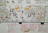
Sorry, maybe I wasn't clear. To be clear, the service manual has a few pages, a section of the service manual, titled "Electrical Parts List" where components are described. On another page titled, "Amplifier PCB Parts Location" it shows R461, R463, R464, and R462 as resistor locations. In these locations, the PCB had no resistors installed, instead they had what are factory installed jumpers.

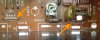
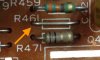
I did see in another thread a pic you posted shows one obviously cooked resistor. … it would benefit you on this project to learn to visually ID the 4 common types of resistors: carbon composition, carbon film, metal oxide, and metal film.
In this receiver, nearly all the resistors are carbon composition (as per the service manual). Those cooked ones I will remove, I think it is worth replacing those because something physical has gone on to merit the same. As noted earlier, resistor values when good were spot on but others are way off — I will check them out of circuit to be sure.
On visually identifying 4 common types of resistors … thank you! I will research this for sure.
Oh and yes, I already checked on resistor so far, out of circuit and its value was spot on. I didn't know this until I saw it. I know that capacitors should be checked out of circuit but I didn't know this applies to resistors. This is why so many had incorrect actual values … I was measuring in circuit. Learning as I go along!

On using the discolored areas as a reference to double check solder points, noted, I shall do this. Granted I have reflowed and when doing so up close, nothing really caught my attention. Still I will check again and research both "cold solder joint" and "halo solder joint".
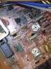
The last paragraph you shared, although split up into a heat related section and a part on acquianting myself with sections of the PCB and schematics. The latter I sense is still some ways away. I spent a lot of time looking at this PCB and it does indeed seem somewhat divided equally, it's not an exact mirror but there does seem to be two equal parts as it were, suggesting that one side is for one L and the other for R speaker.
Roger, I can't thank you enough for devoting so much time and attention to what I am doing. I actually resist posting too regularly on what I am working on. I tend to usually address immediate questions by doing some research first. When I am stuck or what I read is not clear I may eventually show up here for help. I just don't want to bother people too much even though you encourage me to ask. I try to keep things off the spam scale as it were. That said, it's a blessing to have this community forum. Every interaction I have had here has been truthfully, a wonderful experience.
Thank you!





 Made my day, thx.