

You are using an out of date browser. It may not display this or other websites correctly.
You should upgrade or use an alternative browser.
You should upgrade or use an alternative browser.
Passing light through AMP PCB reveals exposure to elevated heat
- Thread starter Alex Santos
- Start date

....... Only two caps were no good, one had the 'can' blown straight out and lying around on the PCB, the leads still soldered in and lots of little bits of silky like paper about.
Alex. Assuming that repairing your amp and getting it working is your goal, this blown up capacitor, and parts surrounding it, is what you should be focusing on.
Ask the forum what could have caused this cap to blow (not here, do it in your next thread which hopefully will include a revised and improved approach). Generally speaking, amp failures can be due to overload (playing too loud, too long or into too small of a load, or short circuit in the speakers or their wiring, or a failed component. In most cases, damage will be in one area and could be as simple as one component, or as complex as a chain of related or connected components.
I am NOT an expert on trouble shooting, but have repaired a few with help from the forum, and also read lots of repair/trouble shooting threads. No expert guiding a newbie through a troubleshooting thread ever advised to remove and measure every capacitor and resistor

You are learning some things though, I grant you.
If ESR and Farad values are good should I solder them caps back in?
I answered this in my first post. My opinion is no. I don't know if everyone would agree. But if the caps are already out I see no benefit in heat stressing the pads and traces more than the one additional time needed to put new caps in. Plus, even if the caps measure good now, their remaining service life will be less than new caps.
I do agree. I hope I justified my approach when it came to electrolytic capacitors above but please advise me..
This applies to the caps, the resistors, the reflowing, etc, pretty much the bulk of what you have done...
Every time the solder iron touches the board there is potential to create new problems. For the people who will hopefully be helping you troubleshoot, there are enough inherent difficulties with troubleshooting remotely when there is a single underlying fault. But when there is more than one underlying fault, troubleshooting becomes much more difficult. Some pads and traces are not robust and could be damaged by repeated or prolonged heat exposure. There are components that can be damaged by solder iron heat (polystyrene caps, small diodes, small transistors, opamps and other ICs) so one must be always be aware of these parts when soldering. Too easy to make a mistake...especially on a first project.
Learning electronic repair often entails learning soldering at the same time, and that increases the chances of something going wrong. If that describes your situation, there is a strong possibility that you are pouring time and effort into an amp that will never work again.
But even if you are already an expert at soldering, not having the ability to test the amp, as it is not currently functional, contra-indicates the massive component removal/replacement effort that you are engaging in.
And even if you have successfully achieved all of those component removal/replacement operations, the mere fact that you have done of of that...with no ability to test for confirmation...could be off-putting to some AK'ers who might be capable of assisting you.
Documentation, being methodical, investing time and effort....those are good things and I commend you for all of that. But removing parts needlessly is not helping the cause of determining what needs to be done to fix the amp, or attracting talented and able people to assist.
On resistors, I had to measure them all, one by one. I am documenting every action, it has taken me days just to do meter the values for resistors.
You didn't have to

I have reflowed all solder joints, removed the electrolytic capacitors, removed the large PNP/NPN transistors flush with the heatsink. Ahh, with these transistors I found one that is not original to this amp so indeed, there was a repair done at one time -
The non-original output transistor is something you should mention in your next thread.
All the removed transistors, their mikas and screws are zip bagged individually to make it easy to put back with some fresh white silicon paste\
How many transistors did you remove?
Those cooked ones I will remove, I think it is worth replacing those because something physical has gone on to merit the same.
The "cooked" resistor I mentioned in my first...I mentioned again in my last post that I was mistaken, that the pic I saw of that cooked resistor was not posted by you. At least I could not find it when I went back to look.
I am guessing that what you perceive to be "cooked" resistors are some showing slight discoloration, if that is the case leave them alone. Please post a pic of what you are calling a cooked resistor so I know we are on the same page.
...and a part on acquianting myself with sections of the PCB and schematics. The latter I sense is still some ways away.
I suggested this for two reasons:
1) it will aid you in communicating with anyone helping you troubleshoot and increase your general knowledge of your amp/receiver
2) at some point you will be selecting new caps. Typical practice is to use some type of audio-specific cap in signal path locations (which appear in the main amp, tone, phono sections, but not in every location in those sections), and a different type of cap for power supply, protection, utility circuits (like meters, etc).
Last edited:
Alex, if you choose to continue working on the NAD, I suggest that you start a new thread in the Solid State forum.
---Put the full model name in the thread title to attract AK'ers who have experience with, knowledge of, or love for NAD in general, or (hopefully) the PE series NADs specifically
---Keep focus limited to the blown-up cap and any other parts that might have sustained damage in whatever event caused that cap to blow, and also mention the non-original large transistor.
---Do not inquire as to what type/brand/model of caps to use as this could easily invite a rush of posts that could derail the thread.There is an ongoing debate/discussion/disagreement on this topic that has bounced from thread-to-thread for years. Gather this type of information for yourself by reading some of the many existing threads or starting your own separately from your troubleshooting thread.
Above suggestions are in my opinion only. I wish you the best of luck with whatever you decide to do.
---Put the full model name in the thread title to attract AK'ers who have experience with, knowledge of, or love for NAD in general, or (hopefully) the PE series NADs specifically
---Keep focus limited to the blown-up cap and any other parts that might have sustained damage in whatever event caused that cap to blow, and also mention the non-original large transistor.
---Do not inquire as to what type/brand/model of caps to use as this could easily invite a rush of posts that could derail the thread.There is an ongoing debate/discussion/disagreement on this topic that has bounced from thread-to-thread for years. Gather this type of information for yourself by reading some of the many existing threads or starting your own separately from your troubleshooting thread.
Above suggestions are in my opinion only. I wish you the best of luck with whatever you decide to do.
Last edited:

cpt_paranoia
Addicted Member
What do you mean by mikas?
Presumably the mica insulating washers between transistors and heatsink; seemed clear in context.

Alex Santos
New Member
Alex. I will address your specific questions later when I have more time. At the moment I will throw out a few quick thoughts
"Measuring component values isn't really the way we diagnose faults; mostly it is done functionally, knowing how the circuit should work, what voltages should exist at various points in the circuit, and tracing a signal through the amp."
The resistors I see in your pics are not carbon composition.
Hi Roger. Didn't mean to ignore your wise points, I must have over scrolled. I will reply point by point.
1) I understand
2) I will keep the removed caps and not put them back in place. I do know where exactly they came from though. These are 35 year old caps, no idea on ESR (no meter right now)
3) For now, I am only measuring those resistors whose values didn't match expected values. My hunch tells me they are ok. Aside from electrolytic caps, I've removed transistors that were lined up against the heat sink. I would like to remove four more just to add new white silicone paste as a maintenance step but I won't for now.
4) Yes I do agree, it doesn't say a whole lot. 3-4 uses out of an amp isn't a confident measure of functionality.
5) Yes, PE is a good design but as 12voltvids (on YouTube) pointed out, these are direct coupled devices so if a transistor or a resistor goes a lot of other parts can go. Good to know that his NAD was also a bit charred in the exact same places as mine.
Yes I agree about the tracing, it's a skill I must acquire!
On resistors, I see only two documented resistor types mentioned in the parts list, Res. Carbon and Res. Metal
Cheers
Alex
Alex Santos
New Member
Alex, if you choose to continue working on the NAD, I suggest that you start a new thread in the Solid State forum.
DO NOT inquire as to what type/brand/model of caps to use as this could easily invite a rush of posts that could derail the thread.
Love it. You have been so helpful! I had a good laugh on the potential derailment warning should the topic of which brand cap comes up. Very funny indeed but I understand that people have a favorite, I can respect that but I won't ask about it or as you say … derailment!
Thanks a million!
Alex Santos
New Member
That's fair. My comment about not measuring every component was a thought …
Only a handful of resistors measure wrong in circuit, once they are out of circuit (only one lead) I get proper values.
....
3) For now, I am only measuring those resistors whose values didn't match expected values. My hunch tells me they are ok. Aside from electrolytic caps, I've removed transistors that were lined up against the heat sink. I would like to remove four more just to add new white silicone paste as a maintenance step but I won't for now.
The resistors that didn't match because their readings in circuit were too low, those you shouldn't unsolder. Assume they are ok. If they measure too high in circuit, then they are out of spec.
Yes, please do not remove transistors for the sole purpose of replacing thermal grease at this point. You may not ever get the amp working again. And every unnecessary component removal lowers your odds of ever getting it working. If as part of the trouble shooting process, someone directs you to remove a transistor for testing, that is when you should do it. Troubleshooting and repair should be done first. If/when the amp is working again, then do maintenance.
5) Yes, PE is a good design but as 12voltvids (on YouTube) pointed out, these are direct coupled devices so if a transistor or a resistor goes a lot of other parts can go. Good to know that his NAD was also a bit charred in the exact same places as mine.
My comment about the PE series of NAD amps was not about whether they are a good or a bad design. It was about the fact that the PE (Power Envelope) NADs are much more complex and more difficult to troubleshoot than other more typical amps. And that when you get to the point of actual troubleshooting, there might be a limited number of people capable of, or willing to, help you.
Yes I agree about the tracing, it's a skill I must acquire!
I should have been more clear on this one, my apologies. I am not suggesting that you learn to troubleshoot your amp by what you call tracing. That would require a massive learning curve that would be unrealistic to achieve without a solid background in electronics.
What I was referring to is how troubleshooting works. And that what you are doing is not that.
Without the electronics knowledge, in order to fix your amp you will need assistance from someone who will guide you through the process. Presently, you are attempting your own troubleshooting process which is more likely to end in failure than success.
That is why I suggest a new thread, but only if/when you are ready to start with a new approach and limit your efforts to identifying the faulty parts, and not removing things for the sake of maintenance or because you have a hunch they could be a little bit off.
Alex I find myself repeating a lot of my points here so I am going to step back. Please do read post #22. I understand that you have been intently involved in your efforts and, having been in that mindset my self, I can relate. And I know it sometimes isn't easy to switch gears.
Last edited:
Alex Santos
New Member
Alex I find myself repeating a lot of my points here so I am going to step back. Please do read post #22. I understand that you have been intently involved in your efforts and, having been in that mindset my self, I can relate. And I know it sometimes isn't easy to switch gears.
Hi Roger, I read your reply. I know that you are rightly trying to have me reconsider my approach and it would be wrong of me to try and challenge someone who knows much more than I.
I will briefly summarize and ask you what I should do next.
- I have already removed all electrolytic caps other than the larger filter caps.
- I have not replaced any of the removed caps.
- I have removed a few resistors, 6 to 9, some of which were clearly burned and measure OL (not in front of my notes now to tell you which).
- I removed the transistors that were installed along the heatsink - I did this first.
- This afternoon I was in the process of taking resistors whose values were not aligned with values documented in the service manual out of circuit. I was going to remove about 10 more resistors to verify their values? Should I stop?
- Should I return the capacitors to their original locations?
- Should I return the transistors other than the one that was obviously there as a result of a repair?
- Finally, should I purchase replacement transistors and resistors (for those mentioned in step 3) and purchase two capacitors to replace the one that was bulged and one the other one that blew up. Well for those 2 caps I will have to.
Should I then build a dim lightbulb switch to see if the bulb goes off? Hopefully nothing blows up.
Please let me know what the best course of action should be and I am sorry for having pulled you in to all this. I will not take any more action until I hear back from you.
Thanks
Alex
Last edited:

cademan
Lunatic Member
If the charred area extends to close to another trace, check for continuity between them -- when the base material of the board itself becomes conductive, you can have current leakage from one trace to another, or across the board to another lead.
I have found this to only be true when working with high voltages like television flyback transformers and their phenolic connections. In this case, it is not something I would worry about.
Alex, I will answer point by point within 14 hours or so. In the mean time please read post #22, in particular the bolded sections. And re-read this entire thread as a lot of good advice has been given.
And please post close-up pics (if your camera can do this) of parts which are known bad, the blown-up capacitor in particular and include a pic of its former position on the PCB, any resistors you suspect (not all of them, just an example or two), and the very worst of the charred or discolored PCB area (not all of the areas). Let's get these pics together in one post and in as concise a manner as possible, meaning only show the absolute worst looking, not everything you have doubts about.
Yes, a dim bulb tester is a good thing to have. But it can only be useful when/if your amp is put back together.
EDIT: And it would be nice to see a picture that shows the entire receiver from the top, with cover off, just for visual orientation and to give us a general idea of what you're working with.
And please post close-up pics (if your camera can do this) of parts which are known bad, the blown-up capacitor in particular and include a pic of its former position on the PCB, any resistors you suspect (not all of them, just an example or two), and the very worst of the charred or discolored PCB area (not all of the areas). Let's get these pics together in one post and in as concise a manner as possible, meaning only show the absolute worst looking, not everything you have doubts about.
Yes, a dim bulb tester is a good thing to have. But it can only be useful when/if your amp is put back together.
EDIT: And it would be nice to see a picture that shows the entire receiver from the top, with cover off, just for visual orientation and to give us a general idea of what you're working with.
Last edited:

I believe that to be correct. But I have not searched for info on them, at least not recently enough to remember anything for certain. Pretty sure that PE stands for "Power Envelope". I had a free, non-working smaller (than the OP's) NAD PE receiver that I passed on few years back.
Quote below from post #2 in the thread linked by Conrad earlier in this thread:
I swore than that never again will I even consider a NAD with a PE designation. Way too complicated - it's like two amplifiers on one chassis
Here is another thread I just found:
NAD 2xxx "Power Envelope" Amp Cautionary Tale or just a Whitewash?
Quote below from post #2 in the thread linked by Conrad earlier in this thread:
I swore than that never again will I even consider a NAD with a PE designation. Way too complicated - it's like two amplifiers on one chassis
Here is another thread I just found:
NAD 2xxx "Power Envelope" Amp Cautionary Tale or just a Whitewash?
Last edited:
Alex, before I answer your post #29 questions, I have a question for you. I mentioned in post #22 polystyrene caps, small diodes, small transistors, opamps and IC's, all parts that can be killed with soldering iron heat. I learned that lesson the hard way on my first amp rebuild. I don't know if your NAD has polystyrene caps, opamps, or ICs (you should find out), but I have not seen an amp that didn't have small diodes and small transistors. During all of the time you have had your soldering iron busy on the solder side of the PCB removing parts and reflowing at least one board, were you conscious of the locations of heat sensitive small parts on the component side of the PCB that are vulnerable to heat damage?
Proceeding from here assumes that you have caused no harm in your previous work...
5) If, when measured in circuit, the resistance readings are higher than the nominal rating of the resistor then yes, remove and replace them with new. I saw your thread about one of the resistors and avionic gave you a good replacement part number. You can trust avionic to give correct advice.
If the resistance readings, measured in circuit, are less than their nominal value then leave them in place for now unless they are visually burned (not merely dicsolored) or they are cracked.
6) For any caps with incorrect values or too high ESR, yes go ahead and get new ones. For the ones that measure good, I am re-thinking my previous advice.
Here's two things that I do know, but that factor in:
---first, your soldering skill? Meaning, that people very skilled at soldering can git parts in and out quickly and with a minimum of heat stress placed on the PCB pads and traces.
---second, how robust are the pads and traces in your NAD receiver? NAD has a reputation for cost cutting on parts, and have no experience soldering on one of them.
Soldering back in the original, but still good, caps now is the easiest way to get you to where your can get into troubleshooting. But if you do get the amp working, most likely you at some point want to install all new caps, which means a second round of heat exposure. So based on what you know at this point, do you feel like the pads and traces in yoru NAD would hold up to a second remove/replace heat exposure cycle in the future?
So what is your level of soldering skill Alex? Are you pretty good, damn good, just learning? Have you had any pads or traces lift in this NAD? Have you ever soldered on other audio gear or other electronics?
7) While the transistors are out you definitely need to diode check them. If you don't know how to do that I will post links. And if your DMM does not have a diode test function you need to get one that does. This is essential for working on audio gear.
Post the model name/numbers of the original transistors and the one replacement. It is possible that the replacement is a good sub. Or maybe it is not.
For all of the transistors I would suggest waiting to reinstall. It is remotely possible that down the road someone might suggest some type of testing with those transistors (which I am pretty sure are the main outputs) uninstalled.
But in the mean time, in case you have not done this already, search for and learn proper method for applying thermal grease, and also what type of grease to use (and not to use i.e. no computer CPU grease). Carefully inspect the mica insulators. If in good condition they can be resued, if cracked or with other flaws, you will need to include them in a parts order.And if you have not already done so, clean the old grease off the transistors and the mica. I use isopropyl alcohol for this task.
Speaking of parts orders, where in the world are you? And which supplier(s) will you be ordering from?
8) transistors: if any test bad, of course new replacements need to be acquired. If the original transistors are still available from a reputable source (i.e. not ebay and not china), then yes make them all match if you can. And yes to resistors or caps or any part that you have determined to be bad. Just don't replace parts because they might not be 100% perfect visually.
9) Dim bulb tester? Probably yes, it is a good tool to have. But I can not be 100% certain that you will get to a point where it will benefit you. If the time or money involved in making a DBT is an issue at all, them perhaps wait until you're sure you can use it. Otherwise, yes go ahead build one.
Please post the pics I requested in post #33.
Proceeding from here assumes that you have caused no harm in your previous work...
...
I will briefly summarize and ask you what I should do next.
- I have already removed all electrolytic caps other than the larger filter caps.
- I have not replaced any of the removed caps.
- I have removed a few resistors, 6 to 9, some of which were clearly burned and measure OL (not in front of my notes now to tell you which).
- I removed the transistors that were installed along the heatsink - I did this first.
- This afternoon I was in the process of taking resistors whose values were not aligned with values documented in the service manual out of circuit. I was going to remove about 10 more resistors to verify their values? Should I stop?
- Should I return the capacitors to their original locations?
- Should I return the transistors other than the one that was obviously there as a result of a repair?
- Finally, should I purchase replacement transistors and resistors (for those mentioned in step 3) and purchase two capacitors to replace the one that was bulged and one the other one that blew up. Well for those 2 caps I will have to.
5) If, when measured in circuit, the resistance readings are higher than the nominal rating of the resistor then yes, remove and replace them with new. I saw your thread about one of the resistors and avionic gave you a good replacement part number. You can trust avionic to give correct advice.
If the resistance readings, measured in circuit, are less than their nominal value then leave them in place for now unless they are visually burned (not merely dicsolored) or they are cracked.
6) For any caps with incorrect values or too high ESR, yes go ahead and get new ones. For the ones that measure good, I am re-thinking my previous advice.
Here's two things that I do know, but that factor in:
---first, your soldering skill? Meaning, that people very skilled at soldering can git parts in and out quickly and with a minimum of heat stress placed on the PCB pads and traces.
---second, how robust are the pads and traces in your NAD receiver? NAD has a reputation for cost cutting on parts, and have no experience soldering on one of them.
Soldering back in the original, but still good, caps now is the easiest way to get you to where your can get into troubleshooting. But if you do get the amp working, most likely you at some point want to install all new caps, which means a second round of heat exposure. So based on what you know at this point, do you feel like the pads and traces in yoru NAD would hold up to a second remove/replace heat exposure cycle in the future?
So what is your level of soldering skill Alex? Are you pretty good, damn good, just learning? Have you had any pads or traces lift in this NAD? Have you ever soldered on other audio gear or other electronics?
7) While the transistors are out you definitely need to diode check them. If you don't know how to do that I will post links. And if your DMM does not have a diode test function you need to get one that does. This is essential for working on audio gear.
Post the model name/numbers of the original transistors and the one replacement. It is possible that the replacement is a good sub. Or maybe it is not.
For all of the transistors I would suggest waiting to reinstall. It is remotely possible that down the road someone might suggest some type of testing with those transistors (which I am pretty sure are the main outputs) uninstalled.
But in the mean time, in case you have not done this already, search for and learn proper method for applying thermal grease, and also what type of grease to use (and not to use i.e. no computer CPU grease). Carefully inspect the mica insulators. If in good condition they can be resued, if cracked or with other flaws, you will need to include them in a parts order.And if you have not already done so, clean the old grease off the transistors and the mica. I use isopropyl alcohol for this task.
Speaking of parts orders, where in the world are you? And which supplier(s) will you be ordering from?
8) transistors: if any test bad, of course new replacements need to be acquired. If the original transistors are still available from a reputable source (i.e. not ebay and not china), then yes make them all match if you can. And yes to resistors or caps or any part that you have determined to be bad. Just don't replace parts because they might not be 100% perfect visually.
9) Dim bulb tester? Probably yes, it is a good tool to have. But I can not be 100% certain that you will get to a point where it will benefit you. If the time or money involved in making a DBT is an issue at all, them perhaps wait until you're sure you can use it. Otherwise, yes go ahead build one.
Please post the pics I requested in post #33.
Last edited:
Alex Santos
New Member
Hi Roger
Sorry for this long post, it was not so easily avoidable. I typed as I went along, excuse the typos.
Note: Removal of components and value measurements was isolated to the Amplifier PCB. Solder reflow was done to the AMP PCB and TUNER PCB.
I do try to keep my dwell times under 3 seconds, just enough time to melt the solder. These solder joints are so small that the dwell time is typically a second or two at most. I also try to remember to keep the iron tip on the pads themselves, not component leads. I am not perfect but I try to follow this principal.
5) Thank you on the resistance readings!
Indeed, one was discolored and another cracked.
Others reveal incorrect values when measured in circuit (as referenced by the service manual). In these cases I desoldered one lead and read the value anew. If the value didn't align with what was documented in the service manual I removed the resistor completely out of circuit and measured the value once more. If the value continued misaligned to that in the service manual I would refer to a resistor color chart to calculate the value as I wanted to rule out a potential documentation defect in the service manual. If the value arrived at from the color chart reflect the measured value I would consider the resistor as good and return it to the PCB.
After describing my process, I see that I should refer to a resistor color chart before removal just to rule out potential documentation defects in the service manual. I have already run into two scenarios; I remove out of circuit and the arrived at value of the resistor matches the service manual and other times it does not.
Sorry to be so lengthy, I wanted an opportunity to layout the steps I take so that you have some bearing on how I am approaching this. If not ideal, please let me know.
6) I have to buy a reliable ESR meter to say with confidence if the caps are healthy enough to return to the board. Can you recommend one? Also, do you know if there are any meters that can reliably read capacitors while in circuit? Is there any truth to this or is it just a myth?
In terms of soldering skills:
I agree on putting them back, it will speed up troubleshooting and eventually (after resolving the amp issue) I should probably replace the electrolytics with a fresh batch. I am of the opinion that the PCB should be able to cope with a few more rounds of solder/desolder/solder. I can't evaluate this presumption completely but from appearances and the reflow paces I put the PCB through don't appear to suggest difficulty in locations where caps would be soldered into. I think my solder skills are pretty good. I am not a pro but am confident and am very considerate of dwell time and where to begin administering the heat, not on the part lead but on the pad.
7 - My multimeter does have a diode mode. I have preliminarily checked the diodes but I want to learn more about measuring PNPs and NPNs. I will work on measuring them.
I am not exactly sure what you mean here. I think you are referring to transistor that I suspect was replaced by someone before I got this NAD in my hands.
If so … Q430 should be the same as Q429. Q430 is not the original transistor It's compliment Q430 is.
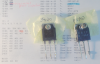
Q429 as per nteinc.com should be
NTE37 (PNP) https://www.nteinc.com/specs/10to99/pdf/nte36.pdf
With DMM in diode mode
Q430 - A1492 has no reading at all - I get OL every which way I read
Q429 - B817E with the DMM's black probe on Base, I get .583 from Base to Emitter and Base to Collector, all other combinations (forward and reverse bias) I get OL.
Thanks for tips on the thermal paste, yes not CPU GPU thermal paste but something proper like white silicone paste. I will inspect those micas to prevent any short. I heard that there are some non-conductive thermal pads that can replace micas and thermal compound. Have to read up on that I guess. And yes I cleaned all the old paste using isopropyl alcohol.
Living in Poland - I can order from Mouser.com even though they are in Texas. Free delivery and duty paid for if order is more than 50 or 100 dollars but there are so many places that I can order from. That's all good.
8) Agreed!
9) Hopefully I will need a bulb dim tester, that would mean some progress has been made.
post #33? - Are you sure it was post #33? I can't find anything in the text that suggest you need pics. I am guessing it was post #31?
R456 - discolored - actual value = 2.879K, expected value = 1K
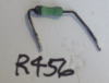
R454 - cracked - actual value = OL

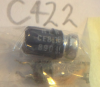
C422 - blown
R307 - Another sign that someone has been inside this amp, see the ink on the PCB under the resistor? Actual and Expected Value = 56K

Thank you so much for your guidance and patience. I can't thank you enough.
I hope this reply does give you some confidence in that I have not just dived in from zero into electronics, granted I have a wealth of knowledge to absorb so in truth I have only hatched out of the egg. I would like to buy an ESR meter to really have confidence in those caps that otherwise measure fine. I would also like to check those few remaining resistors that in circuit, probably for good reason, gave me unexpected values. I am also a bit concerned that some of the smaller transistors and diodes should have their values measured. I can't do much beyond checking the state of components one by one by looking at their actual and expected values. I know that it is incredibly time consuming and doesn't really reflect any troubleshooting methodology but going this caveman approach might help me at least understand that the components in place are fit for purpose. I know that desoldering/solder on an aged PCB does have its risks. I am no where being able to perform some of the magic I see out there, for example xraytonyb
. I just have a lot to learn. I don't want to prematurely turn on this amp until I have looked at everything I can with what I know and as I learn. I appreciate that you've been there.
Cheers!
Sorry for this long post, it was not so easily avoidable. I typed as I went along, excuse the typos.
Note: Removal of components and value measurements was isolated to the Amplifier PCB. Solder reflow was done to the AMP PCB and TUNER PCB.
- Dwell time was between 1-2 seconds at ~300-350°C. Maybe hot but it helps me get in and out quick.
- I will focus answers to just the AMP PCB going forward.
- IC = yes, one 8 pin IC at location IC310
- Polystyrene Caps = yes, none of these have been removed
- Opamps = Maybe this is IC310 (described as a UPC 4570C), the package has 8850R appended to it.
- There are also many small transistors and diodes scattered about.
I do try to keep my dwell times under 3 seconds, just enough time to melt the solder. These solder joints are so small that the dwell time is typically a second or two at most. I also try to remember to keep the iron tip on the pads themselves, not component leads. I am not perfect but I try to follow this principal.
5) Thank you on the resistance readings!
Indeed, one was discolored and another cracked.
Others reveal incorrect values when measured in circuit (as referenced by the service manual). In these cases I desoldered one lead and read the value anew. If the value didn't align with what was documented in the service manual I removed the resistor completely out of circuit and measured the value once more. If the value continued misaligned to that in the service manual I would refer to a resistor color chart to calculate the value as I wanted to rule out a potential documentation defect in the service manual. If the value arrived at from the color chart reflect the measured value I would consider the resistor as good and return it to the PCB.
After describing my process, I see that I should refer to a resistor color chart before removal just to rule out potential documentation defects in the service manual. I have already run into two scenarios; I remove out of circuit and the arrived at value of the resistor matches the service manual and other times it does not.
Sorry to be so lengthy, I wanted an opportunity to layout the steps I take so that you have some bearing on how I am approaching this. If not ideal, please let me know.
6) I have to buy a reliable ESR meter to say with confidence if the caps are healthy enough to return to the board. Can you recommend one? Also, do you know if there are any meters that can reliably read capacitors while in circuit? Is there any truth to this or is it just a myth?
In terms of soldering skills:
- I made mention of two approaches I take that I think are important, dwell time and making contact with the pad and not the lead whenever possible. I feel pretty confident about my soldering skills though.
- The pads and traces do look very good indeed. Even where the PCB has seen elevated heat exposure.
- That said, I did unfortunately manage to loosen a pad and a portion of its trace. It turns out that this portion of pad/trace leads to R456. R456 was completely discolored, the color bands actually unreadable and the through holes visibly blackened by elevated heat. However, I do blame myself here because the evidence should have made it clear to me that at this point I was dealing with a very fragile part of the PCB. Having not clued in as I should have I left the amp on its side and began desoldering the fired resistor out. Firstly the amp should have been lying flat with the trace side facing me. At some point I realized I had to use solder braid to get some of that remaining solder off. The problem here was the solder wick got soldered on to the pad and I lost grip of it, it hung there for a moment and peeled the trace off the PCB, luckily it didn't tear off. Had I been more considerate I would have had the amp lying down not standing on its side where gravity contributed to 'pull down' on the pad/trace.
- To remedy this, I will need to decide if I want to cut off this peeled portion of pad/trace and jumper a wire from the resistor lead to the a portion of trace that remains fixed to the PCB or if the replacement resistor has long enough leads that I can solder on to a good bit of trace still adhered to the PCB substrate. Either way I may need to finish it with some solder mask ink and cure it with UV light. I will research how to glue it back on, which would be ideal, but it might be overly involved in terms of materials and time. Lesson learned here, be extra careful when dealing with burned out parts, the incident leading to failure may have impacted much more than just the component itself.
Soldering back in the original, but still good, caps now is the easiest way to get you to where your can get into troubleshooting. But if you do get the amp working, most likely you at some point want to install all new caps, which means a second round of heat exposure. So based on what you know at this point, do you feel like the pads and traces in yoru NAD would hold up to a second remove/replace heat exposure cycle in the future?
I agree on putting them back, it will speed up troubleshooting and eventually (after resolving the amp issue) I should probably replace the electrolytics with a fresh batch. I am of the opinion that the PCB should be able to cope with a few more rounds of solder/desolder/solder. I can't evaluate this presumption completely but from appearances and the reflow paces I put the PCB through don't appear to suggest difficulty in locations where caps would be soldered into. I think my solder skills are pretty good. I am not a pro but am confident and am very considerate of dwell time and where to begin administering the heat, not on the part lead but on the pad.
7 - My multimeter does have a diode mode. I have preliminarily checked the diodes but I want to learn more about measuring PNPs and NPNs. I will work on measuring them.
Post the model name/numbers of the original transistors and the one replacement. It is possible that the replacement is a good sub. Or maybe it is not.
I am not exactly sure what you mean here. I think you are referring to transistor that I suspect was replaced by someone before I got this NAD in my hands.
If so … Q430 should be the same as Q429. Q430 is not the original transistor It's compliment Q430 is.
Q429 as per nteinc.com should be
NTE37 (PNP) https://www.nteinc.com/specs/10to99/pdf/nte36.pdf
With DMM in diode mode
Q430 - A1492 has no reading at all - I get OL every which way I read
Q429 - B817E with the DMM's black probe on Base, I get .583 from Base to Emitter and Base to Collector, all other combinations (forward and reverse bias) I get OL.
Thanks for tips on the thermal paste, yes not CPU GPU thermal paste but something proper like white silicone paste. I will inspect those micas to prevent any short. I heard that there are some non-conductive thermal pads that can replace micas and thermal compound. Have to read up on that I guess. And yes I cleaned all the old paste using isopropyl alcohol.
Living in Poland - I can order from Mouser.com even though they are in Texas. Free delivery and duty paid for if order is more than 50 or 100 dollars but there are so many places that I can order from. That's all good.
8) Agreed!
9) Hopefully I will need a bulb dim tester, that would mean some progress has been made.
post #33? - Are you sure it was post #33? I can't find anything in the text that suggest you need pics. I am guessing it was post #31?
R456 - discolored - actual value = 2.879K, expected value = 1K
R454 - cracked - actual value = OL
C422 - blown
R307 - Another sign that someone has been inside this amp, see the ink on the PCB under the resistor? Actual and Expected Value = 56K
Thank you so much for your guidance and patience. I can't thank you enough.
I hope this reply does give you some confidence in that I have not just dived in from zero into electronics, granted I have a wealth of knowledge to absorb so in truth I have only hatched out of the egg. I would like to buy an ESR meter to really have confidence in those caps that otherwise measure fine. I would also like to check those few remaining resistors that in circuit, probably for good reason, gave me unexpected values. I am also a bit concerned that some of the smaller transistors and diodes should have their values measured. I can't do much beyond checking the state of components one by one by looking at their actual and expected values. I know that it is incredibly time consuming and doesn't really reflect any troubleshooting methodology but going this caveman approach might help me at least understand that the components in place are fit for purpose. I know that desoldering/solder on an aged PCB does have its risks. I am no where being able to perform some of the magic I see out there, for example xraytonyb
Cheers!
Alex. Thank you for all of the detailed information in you response @ post #35. It will take me some time to absorb, perhaps research a little, and reply to all of those points. I will do so but please understand it will require some time for me to do. I am very busy and have projects, problems, responsibilities etc, just like most people do.
As I work my way through post #35 I think I will address each topic in individual posts, one little chunk at a time. That will make it easier for us to refer to specific points going forward. In this post I will address some of your comments from the end of post #35
But first I have a question for you. As you are living in Poland (prayers are with you, but we are not allowed to discuss politics here at AK), I am wondering whether English is, or is not, your first language?
(1) I believe this has been addressed three times already in this thread. If those resistors, while installed in circuit, measure high, then remove and replace. If those resistors read lower than their nominal resistance value, then do not remove them at this time.
(2) Do not remove any small transistors or diodes at this point in time.
Measuring components directly connected to the known-bad components will make sense but don't start doing that yet. Please allow me time to get a copy of the service manual and dig into it a bit. I will be looking for how these known-bad parts are related.
But...as for removing small transistors and diodes in bulk, it is simply the wrong thing to be doing, and this is the main point that I have been trying to express since my first post. Please acknowledge that the points made in (1) and (2) are understood.
(3) I understand that completely, I have been where you are now. My first attempt at amp repair was to methodically remove flux residue between tracks on the solder side of an amp PCB. It was the only thing I knew to do at the time. I had read somewhere that aged flux residue can become conductive and that in some cases it could cause problems. But I was spinning my wheels (i.e. wasting my time), much like you are doing now. But I have learned a lot since then. I am not the most knowledgeable person in electronics, many here know more than I do. But like you, I was, and still am, very methodical and have the ability to learn. Trust me. I can see where you are, and I believe I can get you headed in the right direction.
(4) Perhaps I did not spell it out completely and clearly, if so I apologize. Simply reflowing can kill components, even if those components are not removed. If you don't already know this, heat can travel in three ways: radiation, convection, and conduction. Conduction is heat traveling through (in this case) metal component leads and PCB tracks. And this heat can damage components. Polystyrene caps are very fragile. I killed an opamp once. All of the small parts mentioned are vulnerable. If a polystyrene cap is damaged you might possibly not even know it.
(5) I have not looked at that video yet, but I will. But I do know how troubleshooting amplifiers works. As mentioned previously in this thread, I don't expect you to learn enough to troubleshoot this amp yourself, that would be unrealistic. But what is realistic is to get you, and your NAD, to a point where you can get troubleshooting assistance from someone with the ability to guide you through it. I can get you there, but again, you will need to trust me even if the path we travel goes counter to what your current knowledge would seem to indicate.
(6) This phrase " ...until I have looked at everything I can with what I know..." makes me wonder if you are determined to remove and measure every component. Please see (2) above.
As I work my way through post #35 I think I will address each topic in individual posts, one little chunk at a time. That will make it easier for us to refer to specific points going forward. In this post I will address some of your comments from the end of post #35
But first I have a question for you. As you are living in Poland (prayers are with you, but we are not allowed to discuss politics here at AK), I am wondering whether English is, or is not, your first language?
........ (1) I would also like to check those few remaining resistors that in circuit, probably for good reason, gave me unexpected values. (2) I am also a bit concerned that some of the smaller transistors and diodes should have their values measured. (3) I can't do much beyond checking the state of components one by one by looking at their actual and expected values. I know that it is incredibly time consuming and doesn't really reflect any troubleshooting methodology but going this caveman approach might help me at least understand that the components in place are fit for purpose. (4) I know that desoldering/solder on an aged PCB does have its risks. (5) I am no where being able to perform some of the magic I see out there, for example xraytonyb .... I just have a lot to learn. (6) I don't want to prematurely turn on this amp until I have looked at everything I can with what I know and as I learn. I appreciate that you've been there.
...
(1) I believe this has been addressed three times already in this thread. If those resistors, while installed in circuit, measure high, then remove and replace. If those resistors read lower than their nominal resistance value, then do not remove them at this time.
(2) Do not remove any small transistors or diodes at this point in time.
Measuring components directly connected to the known-bad components will make sense but don't start doing that yet. Please allow me time to get a copy of the service manual and dig into it a bit. I will be looking for how these known-bad parts are related.
But...as for removing small transistors and diodes in bulk, it is simply the wrong thing to be doing, and this is the main point that I have been trying to express since my first post. Please acknowledge that the points made in (1) and (2) are understood.
(3) I understand that completely, I have been where you are now. My first attempt at amp repair was to methodically remove flux residue between tracks on the solder side of an amp PCB. It was the only thing I knew to do at the time. I had read somewhere that aged flux residue can become conductive and that in some cases it could cause problems. But I was spinning my wheels (i.e. wasting my time), much like you are doing now. But I have learned a lot since then. I am not the most knowledgeable person in electronics, many here know more than I do. But like you, I was, and still am, very methodical and have the ability to learn. Trust me. I can see where you are, and I believe I can get you headed in the right direction.
(4) Perhaps I did not spell it out completely and clearly, if so I apologize. Simply reflowing can kill components, even if those components are not removed. If you don't already know this, heat can travel in three ways: radiation, convection, and conduction. Conduction is heat traveling through (in this case) metal component leads and PCB tracks. And this heat can damage components. Polystyrene caps are very fragile. I killed an opamp once. All of the small parts mentioned are vulnerable. If a polystyrene cap is damaged you might possibly not even know it.
(5) I have not looked at that video yet, but I will. But I do know how troubleshooting amplifiers works. As mentioned previously in this thread, I don't expect you to learn enough to troubleshoot this amp yourself, that would be unrealistic. But what is realistic is to get you, and your NAD, to a point where you can get troubleshooting assistance from someone with the ability to guide you through it. I can get you there, but again, you will need to trust me even if the path we travel goes counter to what your current knowledge would seem to indicate.
(6) This phrase " ...until I have looked at everything I can with what I know..." makes me wonder if you are determined to remove and measure every component. Please see (2) above.
Last edited:
Alex Santos
New Member
Yes of course, I completely understand. Please take your time, your life comes first.Alex. Thank you for all of the detailed information in you response @ post #35. It will take me some time to absorb, perhaps research a little, and reply to all of those points. I will do so but please understand it will require some time for me to do. I am very busy and have projects, problems, responsibilities etc, just like most people do.
I acknowledge the points you made in 1) and 2)
As always, I appreciate the attention you are giving me. I will follow your advice understanding full well that you have more immediate responsibilities and more importantly that you are only able to go so far in helping me because of so many obvious reasons, such as my limited scope of knowledge, distance, available tools etc.
Take your time. I have in fact carefully put everything away while I find a more convenient spot in the house to continue. I was working from the kitchen table while my wife and kids were away on a short vacation.
Thanks again! I did read your message very carefully.
Kind regards
Alex
Last edited:
I am curious about what exactly is your goal and the source of your strong motivations for this project? Is it...
(A) your main goal is to learn to repair audio amplifiers with intentions to take amplifier repair up as a hobby, working on other amps in the future. If you didn't have this NAD you would find a different amp to learn on.
(B) you loved the sound of the NAD that you have the few times when you were able to hear it, and you want to repair it so you can enjoy that sound again. But you do not intend to repair any other amplifiers in the future. And if someone gave you a working NAD 7240PE you would drop this project.
(C) you want to fix THIS particular amp for what ever reasons (which I would like to know). But again (as in B above), you do not intend to repair any amplifiers in the future.
(D) where you live audio gear is scarce and/or very expensive. you need to repair this amp because finding and/or buying another amp would be difficult
(E) something other than what is listed above
(A) your main goal is to learn to repair audio amplifiers with intentions to take amplifier repair up as a hobby, working on other amps in the future. If you didn't have this NAD you would find a different amp to learn on.
(B) you loved the sound of the NAD that you have the few times when you were able to hear it, and you want to repair it so you can enjoy that sound again. But you do not intend to repair any other amplifiers in the future. And if someone gave you a working NAD 7240PE you would drop this project.
(C) you want to fix THIS particular amp for what ever reasons (which I would like to know). But again (as in B above), you do not intend to repair any amplifiers in the future.
(D) where you live audio gear is scarce and/or very expensive. you need to repair this amp because finding and/or buying another amp would be difficult
(E) something other than what is listed above
Last edited:
Alex Santos
New Member
I am curious about what exactly is your goal and the source of your strong motivations for this project? Is it...
(B) is certainly one of them in terms of loving the sound from this amp.
My main system is an Audiolab 8200A and 8200CD so it's not as though I really truly need this NAD per se. Although the Audiolab is very nice I find the sound to be very sterile or cold sounding, it lacks, body as it were. This is true regardless of which speakers I connect up to it and I have tried a couple of different speakers and I get similar results. If I run Audirvana through the DAC I can tweak the sound to be very nice sounding but it involves too many tweaks — something to be said about the old days where a CD is dropped in place and you just listen. The NAD had a certain warmth to it even though it is much cheaper (used). I bought the Audiolab because I didn't want to buy another used amp and risk having problems because I don't have the knowledge to effectuate repairs on my own.
I also really want to learn electronics, this is really a goal of mine. My uncle, who sadly passed away several years ago now was a HAM radio operator and could fix just about anything. He would fix things for the locals and I was really quite blown away by the magic he could pull off. So maybe it would be nice, if I had some foundational knowledge to repair things in the future. It's a nice feeling to be able to repair things. It's rewarding and it helps keep thing out of landfills - so there is that activist side of me that would like to be able to contribute to the circular economy.
Best
Alex
Last edited:
Thanks for that.
FYI a few years back I had a NAD 7225PE that I believe was one step below your 7240PE. I got my NAD in a huge lot of about 30 (mostly) non-working audio pieces that a guy had intended to fix, but he got frustrated and finally decided to dump all of it. Many of the pieces in that lot I did haul directly to the recycle center, but a few others had some value. For the lot I traded him one very beat-up looking Real Tube guitar pedal. So essentially I got it free.
I never worked on the 7225PE as I had lots of other project amps. It had two visibly cooked resistors. I eventually traded it, I think for a cheap but working CD player. I think the reason I never decided to try to fix the 7225 was because I am not a "receiver guy". If it had been an integrated amp I probably would have taken it on as a project. I did have an odd attraction to that broken 7225, though I don't know why. Two pics of it below.
If you could, I would like to see a nude overhead pic of your 7240PE from the same angle and orientation (amp's front to the bottom of the pic) as my 2nd pic posted below. Please make the pic fill up the whole frame so the components are as large as we can make them working within AK's limited jpg size.
I am trying to do from afar, what I would do when starting a project on my own bench. That is, get a good visual inspection and orientation. The pics you have already posted have been helpful, and I might re-post one or more of your pics, but with some specific components highlighted so that I can ask you questions. After that we'll dive into the transistors.


FYI a few years back I had a NAD 7225PE that I believe was one step below your 7240PE. I got my NAD in a huge lot of about 30 (mostly) non-working audio pieces that a guy had intended to fix, but he got frustrated and finally decided to dump all of it. Many of the pieces in that lot I did haul directly to the recycle center, but a few others had some value. For the lot I traded him one very beat-up looking Real Tube guitar pedal. So essentially I got it free.
I never worked on the 7225PE as I had lots of other project amps. It had two visibly cooked resistors. I eventually traded it, I think for a cheap but working CD player. I think the reason I never decided to try to fix the 7225 was because I am not a "receiver guy". If it had been an integrated amp I probably would have taken it on as a project. I did have an odd attraction to that broken 7225, though I don't know why. Two pics of it below.
If you could, I would like to see a nude overhead pic of your 7240PE from the same angle and orientation (amp's front to the bottom of the pic) as my 2nd pic posted below. Please make the pic fill up the whole frame so the components are as large as we can make them working within AK's limited jpg size.
I am trying to do from afar, what I would do when starting a project on my own bench. That is, get a good visual inspection and orientation. The pics you have already posted have been helpful, and I might re-post one or more of your pics, but with some specific components highlighted so that I can ask you questions. After that we'll dive into the transistors.
Last edited: