• The move to the new server is done. There are some software and database maintenance updates in process. This has us passing the hat around to help out. We appreciate any donations. Seriously, even a dollar helps. The payment page may be found here - https://www.audiokarma.org/support.html

Pcb adapter for smd.

Hifibythekg

Super Member
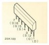
I want to use a JFE2140 (an SMD), recently released by Texas Instruments, to substitute an obsolete 2SK100. (A dual NJFET.)

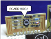
To do so will require a pcb adapter. Can anyone advise as to whether this might be something already available, or would one have to be commissioned?

Or is there another solution?
 
Register to hide this ad
Thanks guys, very helpful.
If searching, would the correct term be ‘pcb SMD adapter’ or is there a specific description I should use?
Also, has anyone successfully/ happily used anything similar to what I propose? I’ll be trying it out in an A-1 or a C4 amp..
 
Thanks much appreciated.
I might need a little more guidance, my apologies.
Space is tight in the area where I want to replace the 2sk100. Also, I’m not confident that I’d select the correct converter.
Could anyone please advise a little further?
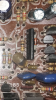
Attached, a couple of pics and links to show you my dilemma. Would have purchased some matched LSK170’s from Linear Systems but being in the UK the shipping costs bring a set up to $90!
Anyway, here’s some pics and specs.
The amps in question are a Yamaha C4 preamp, and a Yamaha A-1 integrated.
 

Attachments

  • 35E5E1BA-9B07-4960-AF79-F7C2573761F5.png
    35E5E1BA-9B07-4960-AF79-F7C2573761F5.png
    865.8 KB · Views: 62
  • BFCEF38D-A29F-42AC-922B-89DFD3B0B3F9.png
    BFCEF38D-A29F-42AC-922B-89DFD3B0B3F9.png
    334.4 KB · Views: 61
  • A611A7DE-27CD-438A-AA06-9B5B2C9D0453.png
    A611A7DE-27CD-438A-AA06-9B5B2C9D0453.png
    214.2 KB · Views: 59
Well the TI part is SOIC8 package. So it looks like you would need to adapt that to a single in-line package but you would need to know the spacing between the leads.

But there is another important factor...the pin-outs. Meaning which pin on the SOIC8 is tied to which pin in the in-line package.

I'm not sure what level your soldering/prototyping skills are at. I've been doing this kind of work for a long time and it very well may be above your skill level...but (if you can't find the correct adapter) I would consider mounting the SOIC8 part on the pcb in what is sometimes called "dead bug" meaning upside down with the leads facing up. you can then connect bus wire from the appropriate leg on the chip to the correct hole in the pcb.
 
Thank you RVT1K.
So, with the Dead Bug approach..
- for bus wire.. can one use any thin wire with a plastic coating/sleeve?
Is there such a thing as a ‘plug’ into which the SMD can be inserted and some wires from the plug can then be soldered to the amp’s board?

The adapter approach..
Might there preexist a ‘SOIC8 to 7 pin inline’ that has all the pins-in and pins-out correctly connected to each other for my situation? So that it’s just a question of one looking up the relevant table and ordering?
 
Wonderful contributions guys. Thank you!

Much thinking out of the box and discovering stuff I didn’t know existed. May well be very close to acquiring an alternative cure for the absence of 2SK100’s!

So to assemble this I would:

1.
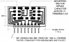
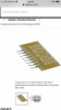
- Solder a JFE2140 onto a Capital Advanced Technologies 9082?

2.

  • Just solder this combined SMD and PCB into the holes in the amp’s pcb where the 2SK100 used to sit. If the pins don’t quite align maybe they can be bent, adapted a little?
But, how do the micro ‘jumpers’ fit in? Please could someone reference the type you mean? Would they have a pre fitted plug at one or each end?

And what if the pins on the JFE2140 don’t match the source/drain/gate of the solder pads on the CAT 9082. Can these be rearranged with the use of jumpers?

Or does one just do this rearrangement after the pins on the CAT 9082?

I think I nearly understand the potential solution, but hopefully one/all of you can further clarify the most rational and elegant way of going about this task as I’ve probably introduced unnecessary and confusing questions..

Hoping that I can then order and assemble the right components to most easily put these things together.

Thanks again.

18A477EF-E4FB-4452-9CD2-ACA4566047E0.png C75EA79C-1A46-4654-AFD4-DE0243EE8638.png
 
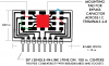
No. Solder the chip to the adapter. The traces on the adapter extend out and have a break in them to put a component inline. Then the trace extends to the pins. The break in the trace is where you could put jumpers to configure the pin out.
 
Dohh...
I see. Thank you for the diagram and explaining this to me.
The jumper wires, please could you recommend anything from Digikey or others that are ideal for this task?
 
Back
Top Bottom