• The move to the new server is done. There are some software and database maintenance updates in process. This has us passing the hat around to help out. We appreciate any donations. Seriously, even a dollar helps. The payment page may be found here - https://www.audiokarma.org/support.html

Pcb adapter for smd.

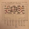
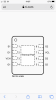
920D2247-1B02-43AB-BBAB-50B99E5C5891.jpeg 67F33D48-8B7D-48A5-A272-1D40EDE37DF2.jpeg Just wanted to check if this diagram correctly describes the paths which the jumper wires should take to allow the JFE2140 to function in place of a 2SK100?
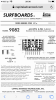
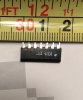
Also, does this wire have the correct spec for doing this task? The supplier suggested that the same spec in 28AWG would also work well.
Found it difficult to just source a short length from Digikey.
https://www.ebay.co.uk/itm/185093022069
 

Attachments

  • 439606BC-EA69-445F-95D1-CAAA428DE54A.jpeg
    439606BC-EA69-445F-95D1-CAAA428DE54A.jpeg
    123.1 KB · Views: 17
  • D1FF4C28-B89F-45A1-BA78-D9DD81CDDFA5.png
    D1FF4C28-B89F-45A1-BA78-D9DD81CDDFA5.png
    362.9 KB · Views: 17
  • 8D2C047D-DD0B-4528-8156-3C0A433D7617.png
    8D2C047D-DD0B-4528-8156-3C0A433D7617.png
    187.8 KB · Views: 16
  • BE8F248D-C4B4-4814-B325-5710605BE65F.png
    BE8F248D-C4B4-4814-B325-5710605BE65F.png
    166.1 KB · Views: 13
  • BF2613D5-B04C-4F08-A97F-F7386305BAF5.png
    BF2613D5-B04C-4F08-A97F-F7386305BAF5.png
    239.9 KB · Views: 13
  • 7FE828D5-6B3F-46B0-994A-CA27987D0185.png
    7FE828D5-6B3F-46B0-994A-CA27987D0185.png
    247.1 KB · Views: 12
Is the spacing correct for the leads that connect to the Yamaha?
You will snip one pin to make ir 7 instead of 8, right?
I don't think you need to connect the Vch and Vcl, do you?
You could go to Home depot and buy a short length of thermostat wire for hookup. They sell it by the foot.
I do not know if this is a good sub for the original part. I know zero about FETs
 
Thanks for the advice Redk9258.
And, yes, will snip one pin to make ir 7 instead of 8.
And, yes, maybe VCL and VCH can just be left alone. Soldered to the adapter’s solder pads but no additional wiring or connection, correct?
Yet to measure the spacing, but this could be tweaked/bent a little if it’s not quite right?
Any experts on FETs and FET matching out there, especially with regard to the context of it being within a Yamaha A-1?
 
I am using jfets in one of my designs and have designed an pcb adapter that takes a lsk489 dual jfet in a sot23-6 to a 6 pin dip
I have also designed my own so-8 to sip adapters
Of course a proper pcb for so-8 to sip for the TI dual would be the best
I think you should be able to use the TI smt adapter pcb for your task, need some small Teflon wire to wire between the adapter and existing pcb, not pretty but doable imo
I’d have to look and compare specs to determine which jfet would be a good replacement for 2sk100
I assume the pin spacings on the sip are 100 mil
 
Thanks RCS16.
So the TI smtadapter pcb would work better than the CAT 9082? Please could you tell me why? Naturally I just want the best solution, and easiest task.
Thanks again.
 
Actually you'll need to snip 2 pins as only 6 pins are used in the inline 7 pin dip the middle pin is not even soldered down.

I might play around in Eagle and try to design acouple boards that can be used in the A-1 to hold two of those chips for drive board
and the single version for the phono stage board. With maybe added through holes for using the T0-92 styli Jfets with a large heatsink pad that you would be able to thermal couple the two .

Might take some time as I am in the middle of a Pioneer RT-1011L rebuild .

Nashou
 
I think the cat9082 would work better unless you have a pcb adapter designed specifically for the components you intend to use for the application
 
Here is a quick image of the layout. Its 19mm wide by 12 mm high . So it can fit in the A-1 drive boards using right angle header.
For the Phono section it might need to lay flat using straight header pins tall enough to go over the other components. Not sure as those 2SK100's are under the EMI shield . I could possible make a lay flat board and use SMD mounted header pins which would make the board about as wide as the chip
as well. It then would hover over the other parts .

51981096080_dfbd9225ce_b.jpg


Nashou
 
Just now looking at how Yamaha installed those 2SK's I might be able to make a single board to
hold 2 of the JFE2140's one on the front and one on the bottom side. Then use surface mount
headers( I think they have them) for the connection to the 2SK board Yamaha uses. I wonder why they used that board and did n to instal them directly tot he main drive board? Might be possible that
there was noise interference if they were installed at close proximity to the main board?

If so these new chips might have better ability to overcome that and be mounted directly to the main
driver board.

Id have to ask on the Yamaha forum i would bet.

Athanasios
 
Nice work and initial thinking.
Yes, would be good to get a view, especially regarding potential noise issues, from some of the Yamaha experts.
Very much looking forward to seeing how well these JFE2140’s perform in practice. Really hoping and expecting them to be excellent, even audibly superior?
But just having them work perfectly well will provide an excellent solution for an obsolete component.
 
Of course a proper pcb for so-8 to sip for the TI dual would be the best
the LSK devices are state of the art and you can match them by rank with older devices.
IIRC, the LSK 389, 489 are dual devices on a single die. Not sure that is the case with the TI, but it would be interesting to figure out.
Nothing against TI. I look forward for some good uses.

Just now looking at how Yamaha installed those 2SK's I might be able to make a single board to
hold 2 of the JFE2140's one on the front and one on the bottom side.

Really hoping and expecting them to be excellent, even audibly superior?

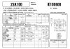
before you guys go down this rabbit hole, has anyone looked at the actual specs of these devices in relation to the SK100? What about rank? would the circuit accept any rank? or work the same with any IDSS? What about transconductance?
 
Cheers @rottalpha for offering advice and insight.
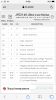
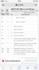
Understanding the specs referred to is above my skill level. Am attaching some specs from TI for the JFE2140, please could you let us know if there’s anything in these that would concern you? Fully recognise that if they seem in the ball park the component still might not be happy in the C4 or A-1, but then again, it might be excellent in situ. But would be very grateful at this point for your assessment.
- I would have gone straight to the LSK matched pairs BUT in the being in the UK, the cost of shipping and import taxes meant that a matched pair would cost $91.77. If the TI solution works this could be a very helpful and cost effective option for others outside of the US.
- Another option suggested is the 2SK109, but I’ve been advised that it’s not very low noise. If the TI should not work out for any reason would you have any experience or opinion on these?
Am aware that LSK 389 of the correct rank can work as a substitute but hard to get hold of them (genuine ones obsolete?) and not as well matched as pairs as say the LSK’s or ...potentially... the JFE2140.
Thanks again.
 
Back
Top Bottom