• The move to the new server is done. There are some software and database maintenance updates in process. This has us passing the hat around to help out. We appreciate any donations. Seriously, even a dollar helps. The payment page may be found here - https://www.audiokarma.org/support.html

Phase Linear 400 and 700B

Just finished testing a 400 tonight.


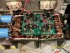
Pic 1 Joe's board in situ
Pic 2 - Don Imlays DC protect
Pic 3 - The big cap is the 470uf/50 volt that improves the low freq response immensely.
The back to back 1N4148's will prevent latch up ,of the positive rail voltage to the speaker posts, which was probably a lot of the flame linear moniker./ The Pl's were pretty unstable durng powerup and this latching up could occur, not now. Eliminates 90 % of turn on/turn off thump also.
 

Attachments
  • 105_1493.jpg
    105_1493.jpg
    115.9 KB · Views: 52
  • 105_1495.jpg
    105_1495.jpg
    103 KB · Views: 53
  • 105_1496.jpg
    105_1496.jpg
    96.4 KB · Views: 55
Last edited:
Ken , IMHO the Series I's sound best, especially with White Oaks new driver board, although it's a universal replacement for the PL 400C, Pl 14A/B, Pl 020, and the Pl o171.
 
Also with Joe's new board you can run the On-Semi 15024's as drivers with the Mj 21196's with no worries of high frequency oscillation.
 
Ken the 700B when I get through with them clip at 510-525 per with an 8 ohm load with both driven, and they sound VERY, VERY good.
 
Ken- for a complete 700 B thread , check this out--http://forums.phxaudiotape.com/sutton-s-phased-linear-white-oaked-1000-rigg-t1616.html
 
I also changed C6 to a 470uf and added the 4148's as per a previous post.
Now just have to get the right side sorted out.
You have been busy.
 
....When I got this 700B it had the Zoebel network on the right speaker outputs toasted and one output on that side shorted.....
Just added one bank on the right, no short according to the dim bulb and the DC is around 30mv. However it sends a loud screech through my test speaker (ouch).
Any suggestions?

Ok you never hook up a speaker while repairing an amp. You get it working with no load first. Then aftr everything works you put a load resistr and do further testing. The zoebal network failed because that channel was oscillating. The cap becomes a short at high frequencis nad puts a lot of power onto the resistor.
 
For Q 1& 2 I used TIS 97's and Q3 & 4 I used 2N5401's.
I changed the blackened cap on the Zoebel.
I did measure the voltage on the PS filter caps and it was identical. But I can't remember the reading. Will have to set it up later and get back to you. I have had wine!

there is a service bulletin that says the 2n5401's failed. they barely meet there Vceo requirement
 
Man I wish I could be your apprentise so I could learn to repair these. I have a lot of Phase Linear amps and I would love to rebuild them all with New caps and output Transistors. I could handle the output Transistors, but I worry about soldering all those caps and resistors without some solder getting over to the next curcuit. I guess my only option is to send it off, talked to d3imlay seems like a good option, I just hate taking chances shipping them along with the cost.


I'm looking for an apprentice to change outputs and make allother repairs. You just have to come to Columbus, oh.
 
.........I guess my only option is to send it off, talked to d3imlay seems like a good option, I just hate taking chances shipping them along with the cost.

Can anyone here tell me, between the different versions, PL 400 Pl 400 with more fins, PL 400 II, what the differences were as far as inprovements that a Listener would notice........

I hav a rsuperb packing system for 400/700s go to U haul and get a legal tote box. Get a sheetof 2" insulation and line the box. remove randles. Put amp in trash bag. put amp in box and wedge with additional foam. Works great.
 
..... Pic 2 - Don Imlays DC protect /QUOTE said:
I have just finished the develo0pment of the 700 output relay. Like the 400 it mounts to the edisting binding posts and requires no drilling. Laatsch55 has installed a few If anyone is interested to know more sne me a PM
 
And they are an EXCELLENT product, very easy to install, exhibit no nusiance tripping and have a relay that will do the job. Thanks again for your trouble Don.
 
Ok, I am back. My board from Joe arrived. Never sorted out the issue on the right channel . Hoping the issue was with the old board. No such luck. Still have the high pitched squeal on the right channel.
I took some voltage measurements to compare the two channels by measuring the the new board's wired connections.
Left Side:
12L: -54V
11L: 54V
10L: 30mv
9L: .455V
8L: 9.7mv
7L:.46V
6L:9.6v
4L: 9mv
3L:-58mv

Right Side:
10R: .662V
9R: 1.3V
8R: 34mv
7R:54mv
6R: 7.5mv
4R:-6.6mv
3R: -52.7V

Looks like the driver on the right side is getting too much voltage?
Note all measurements taken with unit still plugged in to my DIM bulb 200watts.
 
What are 11, 12 on the other channel. HaVE YOU CHECKED THE CAPS ACCROSS THE OUTPUT RAILS TO THE CENTER SOLDER TABS BETWEEN THE ROWS OF OUTPUTS? Have you tested all 4 drivers? Do you have any to swap out with? Check the resistors accross the drivers, 150 ohm I believe, then chck all emitter resistors. Have you checked for continuity between Output cases and ground, like an iffy mica insulator. Have you checked for Ac in the dc and dc in the AC?Lot of things to do here. any trouble with bias, or can you get it off the DBT at all??
 
On the new board there is nothing connected to 12R and 11R.
I checked all the resistors again. They seem fine. I pulled the drivers on the right side and they test fine. The one cap on the right ch output rail is new. Those two resistors were literally blown up when I got the amp so I replaced that cap while I was at it.
At this point I only have one pair of outputs installed on the right side. The left side is loaded.I may have some driver spares if necessary. Still have the original RCA's and lots of MJ21196's.
Where would one test for AC or DC in the wrong place?
I have been adding all new mica's.
 
Sorry it took so long, computer prblems, plus w're in Phoenix visiting the daughter and grandaughter. Do you have jumpers installed going on the backside of the board from 11l to 11R, and from 12L to 12 R??
 
Hey no problems. I have company over as well.
The board was fully built by Joe. So it has three jumpers. One from 11L to 11R.
Nothing between 12L and 12R.
Tomorrow I will take voltages with it off the DBT.
Thank you for your efforts.
Will report back.
 
Fhamre, a 100 watt bulb is plenty to tell whats goin on and will allow more voltage while limiting current. Sometimes a few more volts is all it takes for the frontend to gain contol.
 
Back
Top Bottom