

You are using an out of date browser. It may not display this or other websites correctly.
You should upgrade or use an alternative browser.
You should upgrade or use an alternative browser.
Phase Linear 400 and 700B
- Thread starter Fhamre
- Start date

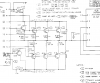

Even though the zoebel isn't on the 400 schematic, it is on the amp and yes the 700II shows it on the schematic.
My relay boards mount on the binding posts. Therefore I had to put the Zobel on the relay board, at the input terminals, to make sure the amp always has the Zobel connected.
If you can post a pic of the tek scope I can tell you how to set it up. Note that you have to use a ground adaptor on the scopes' AC plug to lift the ground. Otherwise it creates a ground loop.
My relay boards mount on the binding posts. Therefore I had to put the Zobel on the relay board, at the input terminals, to make sure the amp always has the Zobel connected.
If you can post a pic of the tek scope I can tell you how to set it up. Note that you have to use a ground adaptor on the scopes' AC plug to lift the ground. Otherwise it creates a ground loop.

Artie
Super Member
Ah, thanks for that info. I've still got a ways to go before I'm ready to start rebuilding this thing, but this thread got me to get it out of the cobwebs.
Right now, I'm reading a bunch of the threads over at the Phoenix forum. Great info over there on the 400/700 amps.
Edit: laatsch55, I just realized that you're the one that did the cool build of a 700 in the thread I'm reading now. Nice work. :thmbsp:
Right now, I'm reading a bunch of the threads over at the Phoenix forum. Great info over there on the 400/700 amps.
Edit: laatsch55, I just realized that you're the one that did the cool build of a 700 in the thread I'm reading now. Nice work. :thmbsp:
Last edited:

laatsch55
Super Member
First do not remove the R/C network. The clue here is the fact that the RC network was blown. This means this amp was oscillating probably above 20khz and since the board has been changed that leaves only the inputs and outputs as culprits. I've never seen it, but the tech manual mentions that pinched insulators can cause oscillations.
Did you reuse insulators? Check the sockets. Make sure that all of the sockets are seated properly in the heatsink. Make sure the outputs and drivers are in properly and you can see the pins in the sockets. FWIW I never pull all of the outputs and drivers out at the same time because of the possibility of the sockets getting misaligned. Try swapping out the drivers and outputs. I would replace them one at a time. this is a last resort.
The input coupling cap shouldn't matter. all the switch does is short it out.
If you need insulators let me know. I picked up about 50,000 silpads (literally) last year at a surplus shop. At the same time I also got about a 1000 kapton TO3's.
I'm guessing you don't have a scope. That would give us some clues.
Don, I was not suggesting he take the Zoebel off and remove it, I believe I said bypass or isolate, to see if it was the source of the squeal, that's all.

Fhamre
Super Member
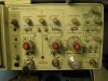
Here is a picture of the 2235.
Not sure what you mean.
Are we talking plugging the scopes three prong plug into one of those three to two prong adapters?
Not sure what you mean.
.Note that you have to use a ground adaptor on the scopes' AC plug to lift the ground. Otherwise it creates a ground loop.
Are we talking plugging the scopes three prong plug into one of those three to two prong adapters?
Attachments
Fhamre
Super Member
So here is an update. On the right side I pulled the single back of outputs I had installed above the drivers. Checked them again for shorts and then chose to install them on the top row. All the while looking for issues with the output banks.
Well tested this configuration. No squelch. Got both channels with nice output.
So logic would suggest an issue with the first output bank on the right side having something touching it shouldn't.
Could a bad resistor be a potential issue as well?
Well tested this configuration. No squelch. Got both channels with nice output.
So logic would suggest an issue with the first output bank on the right side having something touching it shouldn't.
Could a bad resistor be a potential issue as well?
Last edited:
Here is a picture of the 2235.
Not sure what you mean..
Are we talking plugging the scopes three prong plug into one of those three to two prong adapters?
yep. The ground on the scope probes are tied to the AC ground. Need the probes floating.
On the scope set the coupling on each channel to DC. The time base should probably be around 1ms. On the trigger push in the normal button. You would likely have to adjust the trigger level. If that doesn't work push in the Auto button.

Fhamre
Super Member
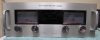
Who is the torque(dork) around here? That would be me. Installed that troublesome bank of outputs with a little less torque. No squelch. Nothing but great two channel sound. Still in testing mode but so far so good.
Really appreciate all the advice and patience.
Really appreciate all the advice and patience.
Attachments
...Installed that troublesome bank of outputs with a little less torque. No squelch. Nothing but great two channel sound. Still in testing mode but so far so good...
I use thumb and index finger loosely holding a nut driver to tighten the screws. When the nut driver turns it's tight. When I'm done with the amp I retighten. I also check transistor temps on the case with a thermocuple to make sure I didn't miss one.
I also wave a hair dryer over the heatsinks from about 12 inches while looking at the bias. The bias should drop with a little heat and then return to normal when the hair dryer is removed. I learned this the hard wway when a 700B didn't thermal track and wiped out all the outputs in one channel. Can't charge for that.