

You are using an out of date browser. It may not display this or other websites correctly.
You should upgrade or use an alternative browser.
You should upgrade or use an alternative browser.
Phase Linear 400 and 700B
- Thread starter Fhamre
- Start date

Fhamre
Super Member
Just using a 100watt in the DBT I started to take some voltage readings. First thing I found was a cooked fuse on the left side supply. I was using 2.5 amp for testing purposes. But that was my last one. So I put in a 5 amp. Then the other 2.5 amp in the other left supply line burnt. Added a 5amp and now the left side indicates a short according to the DBT. The left was my good side. Or so I thought.It was before I added the new board.Hmm, now I am going to pout!

Regardless of which board is in there, troubleshooting is the same. The service manual is excellent in this respect. You look for shorted outputs first. Taking voltage measurements in a direct coupled amplifier rarely gives relevant information because everything has to be working good first.
Check for shorts with the transistors still mounted in the heatsink. If you've replaced them verify proper orientation. The easiest way to check the outputs is to install good fuses and measure resistance from the +/- on the DC caps to the output terminals. If there is a shorted output it will read less than 10 ohms. If you have a short you can determine which one by carefully reading the emitter to collector resistance of each output transistor in the stack. Due to the emitter resistors, the shorted transistor reads a few tenths of an ohm lower than the other ones. The whole point here is to find the problem while making as few changes as possible. That way you have less chance of introducing a new problem.
If there are no shorts and you're sure you've got the board wired correctly, then you have to assume a bias issue. Assuming you're reusing the old bias transistors look for a broken lead or miswire. When I suspect a bias issue I defeat the bias by shorting the base of the predrivers (Q10 and Q7 on PL14 boards) together with a snaggle clip. This is easiest to do at the cathode of D10 and anode of D9. If shorting the bases together allows the amp to come up with the bulb then the issue is in the few components associated with the bias xistor.
Note that you never have a load connected to the amp when using the bulb as the DC offset on the output keeps the power supply from coming up.
I supplied the service manual for common P/L amplifiers in the Digital Docs forum.
Check for shorts with the transistors still mounted in the heatsink. If you've replaced them verify proper orientation. The easiest way to check the outputs is to install good fuses and measure resistance from the +/- on the DC caps to the output terminals. If there is a shorted output it will read less than 10 ohms. If you have a short you can determine which one by carefully reading the emitter to collector resistance of each output transistor in the stack. Due to the emitter resistors, the shorted transistor reads a few tenths of an ohm lower than the other ones. The whole point here is to find the problem while making as few changes as possible. That way you have less chance of introducing a new problem.
If there are no shorts and you're sure you've got the board wired correctly, then you have to assume a bias issue. Assuming you're reusing the old bias transistors look for a broken lead or miswire. When I suspect a bias issue I defeat the bias by shorting the base of the predrivers (Q10 and Q7 on PL14 boards) together with a snaggle clip. This is easiest to do at the cathode of D10 and anode of D9. If shorting the bases together allows the amp to come up with the bulb then the issue is in the few components associated with the bias xistor.
Note that you never have a load connected to the amp when using the bulb as the DC offset on the output keeps the power supply from coming up.
I supplied the service manual for common P/L amplifiers in the Digital Docs forum.
Last edited:
Fhamre
Super Member
Great advice,Don. I actually bought a decent copy of the service manual.
Will go back to the start and check for shorted outputs and read the manual again.
Will tackle tomorrow morning.
When I wired the new board I took my time and followed the wiring chart. I also taped/marked each wire with the old # and new #.That said one can never be sure of anything.
Appreciate your patience.
Will go back to the start and check for shorted outputs and read the manual again.
Will tackle tomorrow morning.
When I wired the new board I took my time and followed the wiring chart. I also taped/marked each wire with the old # and new #.That said one can never be sure of anything.
Appreciate your patience.
Fhamre
Super Member
So after a unplanned delay I am back at the 700B.
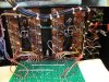
Following Don's great advice. I looked for shorts on the left channel banks of outputs/drivers. Low and behold I spotted a driver lead making contact with a nearby resistor R-38. Eliminating that issue fixed my left channel.
However still have the same issue with the right side. A high pitched squelch outputting from that channel.
I rechecked all the resistors and diodes. I have just the two drivers and one set of outputs installed on that side. I checked them for shorts.
Next I measured for bias on both channels without the DBT.
Both sides check out fine. I adjusted R-20 for both sides to about 375mv.
Also measured for DC at the speaker terminals and get 9.8mv on the left and 7.4mv on the right.
Also rechecked my new board wiring.
Following Don's great advice. I looked for shorts on the left channel banks of outputs/drivers. Low and behold I spotted a driver lead making contact with a nearby resistor R-38. Eliminating that issue fixed my left channel.
However still have the same issue with the right side. A high pitched squelch outputting from that channel.
I rechecked all the resistors and diodes. I have just the two drivers and one set of outputs installed on that side. I checked them for shorts.
Next I measured for bias on both channels without the DBT.
Both sides check out fine. I adjusted R-20 for both sides to about 375mv.
Also measured for DC at the speaker terminals and get 9.8mv on the left and 7.4mv on the right.
Also rechecked my new board wiring.
Attachments

laatsch55
Super Member
Also, cut the ground wire between the RCA jacks and the speaker outputs and run a new 20 gauge or bigger to the star ground point at the bus bar between the PS caps or under one of the 10-32 screws in said bus bar. You can leave the Speaker posts grounded to the white wire going to the 3 terminal strip between the transistor rows, but the one coming off the input RCA's needs to go to the bus bar, by itself.
IIRC, there should already be separate ground wires for each speaker negative anyway.
There is no provision on the White Oak board to accomodate the Direct/normal coupling, how did you deal with that??
IIRC, there should already be separate ground wires for each speaker negative anyway.
There is no provision on the White Oak board to accomodate the Direct/normal coupling, how did you deal with that??
Fhamre
Super Member
Hello!
This is Joe's board it does have the back to back N4148's and C6 is 470uf,25v.
Just not shown in the picture.
Are you supposed to bypass the Zoebel network? When I got this pieces the right side Zoebel was blown. I just replaced it.
Also I didn't know about the "Direct/normal coupling"issue.
What do you do?
This is Joe's board it does have the back to back N4148's and C6 is 470uf,25v.
Just not shown in the picture.
Are you supposed to bypass the Zoebel network? When I got this pieces the right side Zoebel was blown. I just replaced it.
Also I didn't know about the "Direct/normal coupling"issue.
What do you do?
laatsch55
Super Member
Is the switch for the D/N coupling still in??With Joe's board that option is no longer need as his is direct coupled. ON the B's i believe direct coupling bypassed the pots. On the series I's normal added a cap and resistor, direct bypassed those 2 components. So if your B is wired like most there is a lot of questionable stuff in the signal path. That switch is atrocious. I mentioned the Zoebel network as a possible source for the squeal. .
Fhamre
Super Member
Yes, the switch is still in.
Just before I try and sort how to tackle eliminating the switch and possibly bypassing the Zoebel I would just like to mention that my right channel squelch was there with the old board as well.
In my naive way I was hoping the new board would solve the issue.
So where to start?
Just before I try and sort how to tackle eliminating the switch and possibly bypassing the Zoebel I would just like to mention that my right channel squelch was there with the old board as well.
In my naive way I was hoping the new board would solve the issue.
So where to start?
Fhamre
Super Member
I give it a go tomorrow. Don't want to play with a big amp when its getting late.
Will report back. I know I did add another row of outputs with no change. Forgot to mention that. Although when I first put the outputs in ( one row), there was no squelch,but no output. Put the second row in got the squelch. And now have the squelch with just one row.Hmm
Will report back. I know I did add another row of outputs with no change. Forgot to mention that. Although when I first put the outputs in ( one row), there was no squelch,but no output. Put the second row in got the squelch. And now have the squelch with just one row.Hmm
First do not remove the R/C network. The clue here is the fact that the RC network was blown. This means this amp was oscillating probably above 20khz and since the board has been changed that leaves only the inputs and outputs as culprits. I've never seen it, but the tech manual mentions that pinched insulators can cause oscillations.
Did you reuse insulators? Check the sockets. Make sure that all of the sockets are seated properly in the heatsink. Make sure the outputs and drivers are in properly and you can see the pins in the sockets. FWIW I never pull all of the outputs and drivers out at the same time because of the possibility of the sockets getting misaligned. Try swapping out the drivers and outputs. I would replace them one at a time. this is a last resort.
The input coupling cap shouldn't matter. all the switch does is short it out.
If you need insulators let me know. I picked up about 50,000 silpads (literally) last year at a surplus shop. At the same time I also got about a 1000 kapton TO3's.
I'm guessing you don't have a scope. That would give us some clues.
Did you reuse insulators? Check the sockets. Make sure that all of the sockets are seated properly in the heatsink. Make sure the outputs and drivers are in properly and you can see the pins in the sockets. FWIW I never pull all of the outputs and drivers out at the same time because of the possibility of the sockets getting misaligned. Try swapping out the drivers and outputs. I would replace them one at a time. this is a last resort.
The input coupling cap shouldn't matter. all the switch does is short it out.
If you need insulators let me know. I picked up about 50,000 silpads (literally) last year at a surplus shop. At the same time I also got about a 1000 kapton TO3's.
I'm guessing you don't have a scope. That would give us some clues.
Last edited:
Fhamre
Super Member
I don't reuse insulators. 50,000 is more than I have,wow!
I have checked the sockets many times but I should do it again. I did pull them all out at one time to do a thorough cleaning. It was a challenge lining things up. That could be a issue.I did use continuity to try and determine if something was touching something it shouldn't but didn't find anything.
Yes, I do have a scope and signal generator but must admit that me and my Tek 2235 aren't exactly a well oiled team.
I have checked the sockets many times but I should do it again. I did pull them all out at one time to do a thorough cleaning. It was a challenge lining things up. That could be a issue.I did use continuity to try and determine if something was touching something it shouldn't but didn't find anything.
Yes, I do have a scope and signal generator but must admit that me and my Tek 2235 aren't exactly a well oiled team.
