• The move to the new server is done. There are some software and database maintenance updates in process. This has us passing the hat around to help out. We appreciate any donations. Seriously, even a dollar helps. The payment page may be found here - https://www.audiokarma.org/support.html

Phase Linear 400

This BR a good choice ? http://search.digikey.com/us/en/products/GBPC3504A/GBPC 3504A-ND/357380 part #GBPC3504A-ND

If you pull up the Vishay data sheet for the above referenced bridge, the I x I x T (current squared/time) spec is what is most important as that defines the ability of the rectifier to withstand the inrush current. If anyone has a true RMS meter with a current clamp it would be interesting to see what the peak inrush current into the bridge rectifier actually is with both stock and larger capacitors.

I'm guessing it is only 150-200 amps. If so even the 25A Vishay bridge would be more than adequate. The KBH2502 has an I I T of 300A. Sorry, I can't do the test for a few weeks as I have other obligations.
 
Last edited:
I can, got a Fluke 335 with inrush option. Testing a stock 700B to destruction tonight, before doing the complete White Oak conversion.
Finally going to get some baseline info on a stock 700. Got 780 watts of 4 ohm lods sitting in a 5 gallon bucket of ice water. We will be able to answer that question once and for all.

In certain industries field techs use a "water fuse" when working on high power inverters. You put a turn or two of 10A fuse wire around a fuse block and put that in a bucket of water. The water keeps the element cool for normal use. However, if a fault occurs that drives the current up real high the elelments still melts. It clears very quickly as the water snuffs out the arc.

I once saw a load bank in Argentina that consisted of a 55gallon barrel of saltwater. Load was varied by raising and lowering a large plate into the water. Occassionally you had to stir the water and some of it would boil off.

Make sure the line voltage is always the same when doing full power measurements as that directly affects power.

The inrush setting on the meter may be a time averaged reading over 100 milliseconds or so. If available use a peak setting. The ideal way would be to use a storage scope with a current xfmr (C.T.) to capture the first cycle or two. A .01 ohm resistor would also work if a CT is not available. The rectifier time/current spec often lists the time as 8 milliseconds which is 1/2 of a cycel at 60 Hz. (1/60 =16.66ms, 1/2 of a cycle = 8.33ms).
 
A storage scope I do not have Don. I'll check the specs on the Fluke, it may be close enough to give us some useful information.
 
I am starting to recap the amp . Are there replacements or better subs for the silicon transistors for Q1-Q4 just in case? The older germaniun ones must entail a hunt and cash
 
Q1, Q2 -TIS 97's, Q3-TIS-93';s or 2N5087, Q4-MPSA 93.. The 97's were obsoleted last month. If you can't find any, the MPSA 18 will work just fine. Q5, Q10--2N3439, Q7-2N5416. If you can't find any 1304's 0r 1305's let me know I have a few hundred. They are still manufactured by Solid State Inc, but their minimum is a killer.
 
Cornell-Dubilier makes a 18,500 uf 80 volt computer grade cap that fits the original clamps. Could you post a pic of the metyert illumination on your series I, I'm somehat familiar with em.
Still looking for those caps....

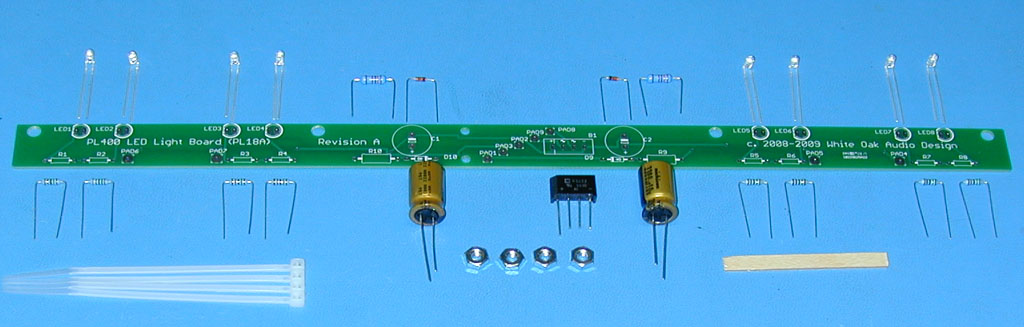
Here are some pics of the rear of the front panel. Looking a the pic of the LED upgrade board it seems it would fit, but in the FAQ they specifically say it won't work in my amp. But.... mine seems to have the 4 wheat bulbs they say will be upgradeable, not the 2 fuse type lamps they warn against. FWIW, my PCB is labeled PL 4M.

Their board:
PL400_Kit_Preform_2_Crop.jpg


My board:
P1030021.jpg


Four little bulbs per side:
P1030021-1.jpg
 
Last edited:
Oh yeah, that'll go in there. Measure the spacing on the mounting holes, should fit. I've never seen a 4 bulb that Joe's LED board WOULDN'tT fit. A pPL 4 board was the predecessor to the PL18. The PL4 had the Honeywell meters I THINK. They might have a different mounting spread come to think of it. One way to tell, set it up on there. The electronics will change over, no problem there.

Pl had so many undocumented production changes it's ridiculous, so being positive about some of their stuff will just embarass you in the end. There could have been a period where the Honeywell mounts were the same for the Dixons, or Jewel's for that matter. Can't find the caps??

Definitely Honeywell meters.

I couldn't find the ones you mentioned (yet). I'd love to use the White Oak board assembly, but they say it won't work for my unit. Don said he has a cap board upgrade, so I might well go that route.

I did find these at Mouser, but they are fatter and shorter than what I have:
http://www.mouser.com/ProductDetail...=sGAEpiMZZMtZ1n0r9vR22WsHOALhvbhWGPa0bfZLODo=
 
Last edited:
This is the PL 18 liight board that Joe's board does replace for sure. The distance between the individual meter mounting holes is 3-31/32's, between the inner holes between the meters, 5-17/32's.
 

Attachments

  • 108_0141.jpg
    108_0141.jpg
    78.9 KB · Views: 23
  • 108_0140.jpg
    108_0140.jpg
    97.7 KB · Views: 22
  • 108_0139.jpg
    108_0139.jpg
    102.6 KB · Views: 22
This is the PL 18 liight board that Joe's board does replace for sure. The distance between the individual meter mounting holes is 3-31/32's, between the inner holes between the meters, 5-17/32's.

Looks like it'll work, then. Thanks!

I just finished putting one of Don's cap kits in his own 400 Ser II. Nice cap upgrade, very handy.

Cool. As soon as I'm finished installing Don's relay solution, I'll hit him up for more information. :)
 
It looks like I have to move R6 ( to the foil side ?)or it will be underneath C6. Also what do you think about changing the whole board to 1% metal flim resistors ? Pros & Cons of metal film resistors anybody?
 

Attachments

  • MVC-005S.jpg
    MVC-005S.jpg
    119.1 KB · Views: 31
Metal film are non-inductive and what the White Oak board uses. If you are going to that trouble, get Joe's board. 20.oo for the board and 70.00 for the components. He has a BOM registered at Mouser. One click and all the parts can be ordered. If you want I will post a link.
 
I already have the resistors. I've seen the board on the White Oak site .Just something I'm thinking about . Go ahead and post the link though , thanks, What about moving R6 ?
 
Back
Top Bottom