• The move to the new server is done. There are some software and database maintenance updates in process. This has us passing the hat around to help out. We appreciate any donations. Seriously, even a dollar helps. The payment page may be found here - https://www.audiokarma.org/support.html

phase linear - dual 500 series 2, diagnostics plus updates and some thermals

sae-7125

Super Member
dusting off the amp and achieving a stable pulse under controlled conditions. why did they decide an oddball fuse size (physical) was a good idea (agx-8).

found a schematic and basic info on a few sites including ak but still hunting for a service manual that isnt behind a paywall (sites selling documents) or another forums registration barrier.

dc bias was mentioned to be around 325mv measured across a 10r resistor amongst the moderate mess soldered to the output devices. on the small board mounted to the heat sink rear of the chassis i am noticing 3k 3w power resistors instead of 3k 5w as stated on the schematic. this amp has a serial number a couple numbers below 1600, wonder if there were a few versions/revs of this model.

so the journey begins with fuse shopping and some cleaning while determining possible design quirks to update. other sources have indicated unbundling the wire harness due to noise bleed of parallel conductors and converting the system to a star ground wiring scheme. also some talk about adjusting a resistor value from 680r to 860r or 1k in regards to bias circuit.

the class-b design is nice due to its natural high efficiency but crossover distortion at low volume levels is common. bumped into the "pink floyd way" of cooling the amp by packing the heat sink with dry ice, i have no idea how accurate that description might be. other than the commonly held title of "flames linear" and a few other metaphorical variances this brand of pre carver corp amplifiers has a pyrolytic history with consumers.

i am using a normal length 7a fuse as a temporary fast blow alternative to evaluate slow power up activity of the amp (variac plus dim bulb). so far things seem functional with mains dialed up to 110v. currently have bias at minimum to reduce initial load factor on the power supply even though this is class-b. display board needs some updates since the dancing red dots are a little bit cross-eyed/stuck with or without signal applied. 8r test speakers used with the high-z mode, looks like lower dc bus voltage if using low-z after reading up about the two different dc bus modes (125 vs 80).

PL-01.jpg
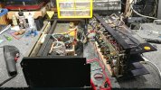
the heavy monster amp, back when an all metal chassis was the norm.
PL-02.jpg
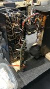
rats nest plus umbilical of noise potential.

PL-03.jpg
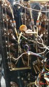
rear pcb, at least its easy to service.
PL-04.jpg
reminds me of last years sae amp.
 
Register to hide this ad
All of the .39 Ohm resistors in the output stage are actually wire wound resistors as signified by the double wide orange color band. The SPH series by TT Electronics is currently available and datasheet confirms this.

Craig
 
Last edited:
They were still using some CC resistors on the driver boards in that era though. I worked on a 700 Series II from 1978 that had a lot of off-value ones. This one looks to be mostly carbon film though, which is a good thing.
 
carbon comp resistors
there are a few on the pcb that will be replaced. should be interesting to see how many are under face plate.

looks like d2 is germanium (1n34), that will need an update. heat + germanium component usually equals reduced lifespan. thank goodness not as bad as sae gorler tuning gang brain surgery, been there done that although the nixies were enjoyable.

looks like the 3k 5w (schematic) steps down rail voltage to help the 15v zener last longer. still a massive thermal event on the pcb, the 3w components in this particular board were sitting on the pcb, hello discoloration.

anybody have access to hifiengine and snag the service manual for the benefit of akdatabase.org? looks like most of the other phase linear models are listed.
 
All of the .39 Ohm resistors in the output stage are actually wire wound resistors as signified by the double wide orange color band. The SPH series by TT Electronics is currently available and datasheet confirms this.

Craig
Ah, that makes sense then, thanks.
 
I have a connections here and there. I'll see if I can find you the full service manual. That's one BAAAD mama jama right there?
 
That photo of the rear pcb brought back bad memories from my last job.
One of the units I regularly saw to repair had boards that looked just like that. No reference designators and the traces would come off with very little provocation. Add mulitple revisions with no markings on the boards to identify which just landed in front of me. I used to joke that they were manufactured in someone's kitchen.
 
I know what you mean. I just finished an Akai AA-1050 that had obvious revisions that were not listed in the S/M and, if they were ever published anywhere, I can't find. That, and no component locations either side of the boards. Actually, there was nothing at all silk screened to any board on either side. I have seen many units like that. It adds time to repairs and leaves the 'oops door' wide open.
 
It's bad enough to find stuff like that in home audio equipment and kind of understandable considering that age of stuff and the state-of-the-art at the time.

But..

I was working for a company that made E-beam lithography tools that cost in the neighborhood of 2 Mil USD.
I offered to re-layout the boards and have new ones made to bring things up to a decent standard. My request was shot down because the unit was allegedly being phased out. I'm willing to bet there are dozens out there.
I got the last laugh and retired early. Not my problem any more!
 
What is this 'retired' of which you speak? My guess it's something I will never get to do,...

A glorious state of affairs where one no longer has any responsibilities above and beyond figuring out what bit of yard-work I want to do if any or how many times will I go out to the pool.

One of the best things that ever happened to me was my dad making me sign up for the company 401k (thanks, dad!!) way back when. I had NO CLUE at the time -I was in my early 20's- how important it is to start saving for retirement.

We sold the house and car and moved to Belize in May of 2022. The sale of the house financed building a new home here and we have no mortgage. Property taxes and health-care costs a shockingly low here.
 
That sounds fantastic. But, I'll never get to that point. I had to cash out 24 years' worth of 401k in 2007. Long story that involves an ex wife. Started over with $375 to my name and a Jeep I still had payments on back in 2008. I'm over it and doing very well now, but retirement does not look like an option. Enough boo-hooing out of me, though.
 
dusting off the amp and achieving a stable pulse under controlled conditions. why did they decide an oddball fuse size (physical) was a good idea (agx-8).

found a schematic and basic info on a few sites including ak but still hunting for a service manual that isnt behind a paywall (sites selling documents) or another forums registration barrier.

dc bias was mentioned to be around 325mv measured across a 10r resistor amongst the moderate mess soldered to the output devices. on the small board mounted to the heat sink rear of the chassis i am noticing 3k 3w power resistors instead of 3k 5w as stated on the schematic. this amp has a serial number a couple numbers below 1600, wonder if there were a few versions/revs of this model.

so the journey begins with fuse shopping and some cleaning while determining possible design quirks to update. other sources have indicated unbundling the wire harness due to noise bleed of parallel conductors and converting the system to a star ground wiring scheme. also some talk about adjusting a resistor value from 680r to 860r or 1k in regards to bias circuit.

the class-b design is nice due to its natural high efficiency but crossover distortion at low volume levels is common. bumped into the "pink floyd way" of cooling the amp by packing the heat sink with dry ice, i have no idea how accurate that description might be. other than the commonly held title of "flames linear" and a few other metaphorical variances this brand of pre carver corp amplifiers has a pyrolytic history with consumers.

i am using a normal length 7a fuse as a temporary fast blow alternative to evaluate slow power up activity of the amp (variac plus dim bulb). so far things seem functional with mains dialed up to 110v. currently have bias at minimum to reduce initial load factor on the power supply even though this is class-b. display board needs some updates since the dancing red dots are a little bit cross-eyed/stuck with or without signal applied. 8r test speakers used with the high-z mode, looks like lower dc bus voltage if using low-z after reading up about the two different dc bus modes (125 vs 80).

View attachment 2949105
the heavy monster amp, back when an all metal chassis was the norm.

View attachment 2949106
rats nest plus umbilical of noise potential.

View attachment 2949107
rear pcb, at least its easy to service.

View attachment 2949108
reminds me of last years sae amp.
dusting off the amp and achieving a stable pulse under controlled conditions. why did they decide an oddball fuse size (physical) was a good idea (agx-8).

found a schematic and basic info on a few sites including ak but still hunting for a service manual that isnt behind a paywall (sites selling documents) or another forums registration barrier.

dc bias was mentioned to be around 325mv measured across a 10r resistor amongst the moderate mess soldered to the output devices. on the small board mounted to the heat sink rear of the chassis i am noticing 3k 3w power resistors instead of 3k 5w as stated on the schematic. this amp has a serial number a couple numbers below 1600, wonder if there were a few versions/revs of this model.

so the journey begins with fuse shopping and some cleaning while determining possible design quirks to update. other sources have indicated unbundling the wire harness due to noise bleed of parallel conductors and converting the system to a star ground wiring scheme. also some talk about adjusting a resistor value from 680r to 860r or 1k in regards to bias circuit.

the class-b design is nice due to its natural high efficiency but crossover distortion at low volume levels is common. bumped into the "pink floyd way" of cooling the amp by packing the heat sink with dry ice, i have no idea how accurate that description might be. other than the commonly held title of "flames linear" and a few other metaphorical variances this brand of pre carver corp amplifiers has a pyrolytic history with consumers.

i am using a normal length 7a fuse as a temporary fast blow alternative to evaluate slow power up activity of the amp (variac plus dim bulb). so far things seem functional with mains dialed up to 110v. currently have bias at minimum to reduce initial load factor on the power supply even though this is class-b. display board needs some updates since the dancing red dots are a little bit cross-eyed/stuck with or without signal applied. 8r test speakers used with the high-z mode, looks like lower dc bus voltage if using low-z after reading up about the two different dc bus modes (125 vs 80).

View attachment 2949105
the heavy monster amp, back when an all metal chassis was the norm.

View attachment 2949106
rats nest plus umbilical of noise potential.

View attachment 2949107
rear pcb, at least its easy to service.

View attachment 2949108
reminds me of last years sae amp.
I now have the complete service manual for this unit, complete with bulletins. It's too big to upload here, according to the message that popped up. How can I get it to you??
 
a few updates although it will take a few posts to organize measurements and thermals.

PL-11.jpg
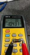
aged carbon comp resistors, like playing lotto ez-pick never know what numbers your going to see.


PL-12.jpg
obviously the 2 resistors are suppose to be 7.5k, apparently its bring your quantum hysteresis to work day or something.

PL-13.jpg
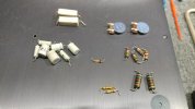
small pile of parts, not including the 2 dozen+ caps from the meter board.

PL-14.jpg
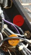
apparently this amp goes by the name of diane.
 
That sounds fantastic. But, I'll never get to that point. I had to cash out 24 years' worth of 401k in 2007. Long story that involves an ex wife. Started over with $375 to my name and a Jeep I still had payments on back in 2008. I'm over it and doing very well now, but retirement does not look like an option. Enough boo-hooing out of me, though.
I went through that about the same time, and still have my Jeep. :biggrin:
I'll probably be buried in it. At leased it has never let me down. :rockon:
 
and now for some snapshots of thermionic emissions, of a sort.

PL-a1.jpeg
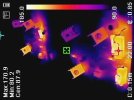
thermal camera reference photo to show amp and pcb positioning as it relates to the physical world i.e. tech bench.

PL-a2.jpeg
high-z mode, 8r speakers, amp playing signal at low volume. r101/r126 modified from 3k 3w original to temporary collage of resistors (6.8k 5w // 11k 1w //11k 1w = ~3040r 7w). with around 102v across r101/r126 each the following can be calculated 102^2/3040 = 3.422w. perhaps using a 3500r 6w upgrade will be a good idea? it is not surprising the pcb started to discolor, in some cases indicating this amp has relatively low hours on it. for a 3w component to be in close proximity to a generic 85c rated electrolytic (c102) not to mention d101/d114 15v zeners are a few mm away from r126 (d101 can make physical contact quite easily... not good thermally speaking) this seems like a catastrophe waiting to occur (at high-z idle). r102 (7.5k 2w) is a cooker as well (86.6v^2/7500 = 1w, not as severe).


PL-a3.jpeg
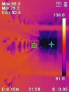
now the amp is in low-z mode, same setup and conditions as mentioned above, look at the thermal decrease due to lower dc rail to rail voltages.

PL-a4.jpeg
a view down the center corridor, vertically speaking, at idle so no thermal carnage to see here. also no single output device showing signs of thermal/electrical dysfunction. for some odd reason this reminds me of "i'm afraid i can't do that, dave".

PL-a5.jpeg
a view of the transformer and the three little pigs under their metal tent (industrial sized relays x3).

PL-a6.jpg
an overall view of things, looks like i was monitoring dc bias setting on the left channel which was set to 160mv on a 75w capable dim bulb setup. at full mains (off the chain, very dangerous) the bias went up to 182.5mv (lower than i was expecting) and i think this was in low-z mode since high-z was over 280mv. i am starting the amp at low dc bias for output transistor safety reasons and to monitor potential thermal runaway which typically ends in a kaboom event (such a mood killer when that happens).
 
Back
Top Bottom