• The move to the new server is done. There are some software and database maintenance updates in process. This has us passing the hat around to help out. We appreciate any donations. Seriously, even a dollar helps. The payment page may be found here - https://www.audiokarma.org/support.html

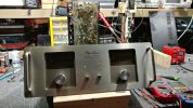
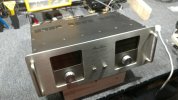
phase linear - dual 500 series 2, diagnostics plus updates and some thermals

the 120vdc to 85vdc is controlled by the front panel hi-z/lo-z switch. plus there is a detection circuit if distortion is detected in hi-z mode, it will automatically drop to lo-z.
so basically like modern cheap amps with a 4 ohm / 8 ohm switch on the back. It drops the rail voltage to keep the power output within what the output devices can actually handle. Nice that it will auto-switch in an effort to save itself though.
 
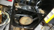
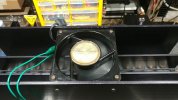
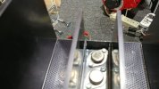
fan shows airflow towards the transistors, as one would expect for ideal cooling.

fan-1.jpg
definitely not a cheap cpu fan equivalent.

Screenshot 2023-08-02 at 12-18-29 Phase Linear Dual 500 Diagnosis Assistance Requested.png
there is some mention on another forum about somebody who makes a different LED board.

Screenshot 2023-08-02 at 12-18-50 Phase Linear Dual 500 Diagnosis Assistance Requested.png
2 different modes.

Screenshot 2023-08-02 at 12-23-17 Phase Linear Dual 500 Diagnosis Assistance Requested.png
bias measurement locations.

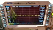
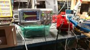
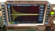
i will be posting inrush measurements next, looks like around 160a pk-pk which equals 56.5a rms for the first full waveform and then reduces down to a rather disfigured idle waveform.
 
a few oscilloscope snapshots and waveforms.
inrush-1.jpg
a rather messy layout, needed a larger variac since beyond 110v mains tends to pop a 5a fuse (500va variac in background).
inrush-2.jpg
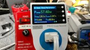
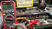
idle numbers hi-z mode, dc bias around 350mv each channel, 8r speakers connected.
inrush-3.jpg
power caps were discharged down to below 1v prior to every inrush measurement. fairly uniform inrush wave.
inrush-4.jpg
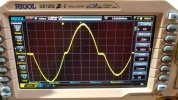
focusing on first 16ms (60hz) wave to see max stress on startup. poor little 5a variac fuse, never stood a change against that magnitude of inrush.
inrush-5.jpg
one rail voltage when amp is fed 120v mains. something to note when comparing to 125v rated filter caps.
inrush-6.jpg
idle numbers for lo-z mode, dc bias around 300mv, i should do an inrush scope photo for this mode (forgot to do so) to compare with hi-z.
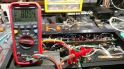
inrush-7.jpg
one rail voltage in lo-z mode.

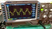
idle wave.jpg
and this is the odd waveform when measuring in real-time (amp idle, hi-z). bob is doing a lot of weird things under the hood unless this is textbook class-b.

 
updated parts pile.

parts-2.jpg
the 2.7k resistors in front row, almost center, were cooking around 200f at idle. now using a pair of 1w replacements in parallel, idle temp around 140f.
 
I'm wondering if running the caps to their absolute limits was just a Phase Linear thing. The 700 has 100v caps, mine was running at 107 volts. The new ones are rated 160v. It sounded much better just from changing those main filters than I ever would have expected.
 
running the caps to their absolute limits was just a Phase Linear thing.
there are a few other brands that run power caps at max voltage which leaves little to no safety buffer. most vintage gear txf's were designed for 110v or 115v or 117v so when feeding the ratio device (the mains txf) 120v things are already at or beyond a safe zone. running some sansui gear at 100v mains drops the idle temp favorably, which extends lifespan. i constructed a thread about sansui au-717 and au-719 measurements, it is informative.

i will measure the phase linear rails when the system is supplied with 125v mains since not all power grids are balanced equally. it should help give a better idea as to an upper limit.

It sounded much better just from changing those main filters
updating the big filter caps tends to yield noticeable improvements, bump up their value from 13000 to 18000 or 22000 and things get even better. i was contemplating a pair of 51000uf 160v caps but things get expensive quickly. due to the naturally high inrush current of the dual 500 adding bigger caps will need a mod involving a soft start relay or some healthy sized ntc thermistors. mcintosh used thermistors in some of their designs. fun stuff...
 
looks like a useful and cost effective soft start module. a few options exist on amazon when doing a search for "soft start module". idea shopping more than anything.

i should have more measurements and testing data later tonight. if all goes well the amp will be ready for prime time demo'ing. the ceiling tiles typically hate high dynamics exercising of amplifier+speakers, light fixtures not too fond of it either.
 
lo-z mode has less abusive inrush although txf buzz seems more prominent vs hi-z.

inrush-low-1.jpg
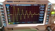
155a pk-pk = 54.79a rms, not a significant decrease vs hi-z except the the system settles down quicker. fewer stressed components at idle temp.

inrush-low-2.jpg
stretched waveform, quicker ramp down even though 80v rails still pack a punch.

inrush-low-3.jpg
idle waveform still looks as odd as hi-z posted earlier.
 
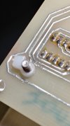
i seem to have bumped into a rather odd and potentially damaging design issue with the display board.

nuts-1.jpg
i replaced the electrically conductive metal nut with a non-conductive zip tie until a more suitable nylon washer is found. shorting the exposed traces to chassis ground seems like a bad idea.

nuts-2.jpg
same location, view from another angle.

nuts-3.jpg
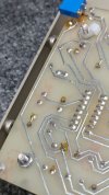
another potential electrical short to chassis ground. opposite side of the pcb. new 5k pot making a cameo appearance, normally lives in seclusion next to a toasty warm txf.
 
measuring the effects of a mild over-voltage situation (ac mains 125v) while in hi-z mode.

over-volt-1.jpg
brief evaluation of a slight mains voltage jump, many domestic utility companies specify a max/min residential service voltage.

an interesting, yet brief, conversation on the topic:

over-volt-2.jpg
still below 125v power cap rating but... when factoring in age of capacitors and an increased voltage drop on many high wattage components (like the 3k 5w twins) this situation can be highly problematic. in this measurement 125v mains = 123v rail (+/- - 246v) = 108v across the 5w resistors (123v - 15v zeners). looking at 3.88w power disipation almost 4 of the 5w component tolerance. and this particular unit had 3w resistors from the factory, i wonder how many other units are in a similar situation??
 
dc bias settings and stability measurements.

bias calibration.jpg
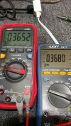
using 2 dmm's to monitor both channels during adjustment and low signal performance reaction.

bias meters.jpg
hi-z mode idle, stable set point between channels.

bias final idle.jpg
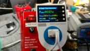
idle numbers for the ~365mv bias settings, obviously no dim bulb (wattage choke chain) involved.

the bias numbers drop to around 275mv in lo-z mode +/- 5mv between the channels. overall sonic performance seems decent, not too bad with detail and sound stage width. low volume is relatively good especially vs dc bias set to minimum (noticeably crunchy for obvious reasons). a few more things to do and then off to the demo chamber and into the wild.
 
new location for zeners and r105/r205 which feed the bias circuit.

zener pcb.jpg
zeners moved to reduce thermal damage potential. original 2.7k were discoloring from high heat dissipation, bumped up to a pair of 1w in parallel.
 
cooling fan testing and air flow evaluation.

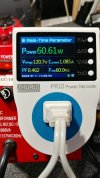
cooling fan watts.jpg
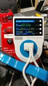
fan consumption, ac mains direct connection to fan.

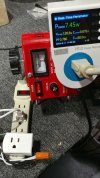
cooling fan.jpg
fan spins without issue, no age/gunk related noises regardless of horizontal or vertical position.

cooling issue.jpg
in terms of air flow on/over/around/through the heated surfaces... i wonder if these end transistors have a higher failure rate? the thick metal screen can block some air flow (one area of inefficiency) but to have a wall that is sabotaging optimal air flow seems problematic. i suppose removing all the metal screens would be an ideal mod but it runs the risk of exposed high voltage dc to any kind of oops event.

the high density of output transistors on a common/shared heat sink guarantees an quick space heater under high output conditions. which in turn subjects all outputs to reflected heat by the neighboring components. since the stock outputs are rated for 200c that might be part of the magic design sauce implemented. i wonder if using half as many outputs although rated for higher wattage would balance the thermal intensity better? a nit pick analysis but it would be interesting to see what little is needed to make something good even better.
 
the insulating covers are an interesting thought. one concern would be the 130c continuous use temp, although this amp could spend most of its uptime around 85c/185f which would be no problem. its the 1 or 2 hour thrash on a friday night (+/- beer/pizza) that could easily hit a sustained 150-180c which would give the cooling fan a run for its money, that would be my concern.

a few anodized narrow strip (low thermal resistance) heat sinks might be a possibility. something that is narrow enough to allow air flow around the transistors but also mop/sponge the thermal carnage via a thin finned sink on the top of the rows of outputs. a heat spreader similar to what is used on ddr5 ram sticks or m.2 ssd's. speculative engineering at this point, although a negative energy system (floyd sweet) would take things in a completely different quantum vector.


unfortunately the overall metal chassis seems to be minimally ventilated and no significant thermal exit for the monster txf under the hood. that might explain why some touring companies typically relocated the txf to an external position.

vents small.jpg
chassis venting might be better than nothing but...

it would be best to run the amp in lo-z mode, especially when turning it on, improved life span of some important components. best to update/overhaul a new acquisition without an initial power up. after a few decades of living in storage this ogre is not like an onion regardless of its layers.
 
Back
Top Bottom