• The move to the new server is done. There are some software and database maintenance updates in process. This has us passing the hat around to help out. We appreciate any donations. Seriously, even a dollar helps. The payment page may be found here - https://www.audiokarma.org/support.html

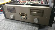
phase linear - dual 500 series 2, diagnostics plus updates and some thermals

special thanks to @Tech45 for the phase linear dual 500 series 2 service manual. after skimming through it there seems to be a nice amount of info.

**also includes service bulletins. very awesome...

original pdf sliced and diced using:

free software i have been enjoying for more than a few years, perhaps decade+.

for my posted photos this is used:

internet browser (plus loads of add-ons):
 

Attachments

Cool. I just have a thermal gun. I've run across hot running higher watt resistors that were right on the board. I replace them and leave some space between them and the board, bending them away from other components like caps if possible. I don't understand why some manufacturers didn't leave some air space between the resistors and board. And then using 85° caps. I've also added or placed better heat sinks on transistors on the amp boards and hot regulators in the power supply. Anything to get the heat lower is a plus.
I had a Pioneer receiver I went through and gave to one of my son's that had a regulator that runs very close to its max current draw. The board was black and I've read in some instances the solder even got hot enough to melt. I added a heat sink to it and it runs much cooler now.
With the type of heat sinks that were used in your amp board, I've added a second to the back side a few times that helped to keep the device cooler when room allowed.
 
I don't understand why some manufacturers didn't leave some air space between the resistors and board. And then using 85° caps.
in some cases it is a mystery that may cause insanity should we ever figure out why they did what they did back in the 70's. on the other hand we can make some logical deductions as to the state of manufacturing affairs back then.

capacitors were far more expensive in the 60s/70s/?80s to the point that using the bare minimum capacitance (for electrolytics at least) that they could get away with (device/amplfier/consumer electronics) and still achieve reasonably decent function regardless of longevity was the primary design goal.

xraytonyb youtube channel has some great info about such thoughts and ideas.

from what i have seen and measured and repaired across the various vi-fi brands (vintage fi) is that "parts cooker syndrome" was the norm, design wise. what do you suppose happens when a significant amount of heat is applied to an electrolytic cap? the electrolyte expands and so does the capacitor (or condenser if your kicking it old school) plates which... increases capacitance. it is interesting to think that when people/reviewers say that an amp or other piece of sonic splendor sounds "better" after it has "warmed up" one could attribute that outcome to the cooking of electronic components so that they are out of tolerance which happens to be closer to being in-tolerance for optimal sound.

this is a somewhat radical hypothesis i find myself constructing and evaluating over the years even though other forums/threads tend to find it a bit of a stretch (my recent activity with sansui regulars). not quite to the point of getting burned at the stake for being a nut job but possibly not too far from it.

to each their own... within reason. and thats where many things fall down.

after doing an "XL" mod on an mc-2105 the results were sonically pornographic, depending on a persons preference for hard hitting low frequency response and sound stage detail+width. it involved some minor tweaks (rear screen needed a lift kit) but also compensating for current inrush when going from 39000uf x2 up to 0.1f x2 for the filter caps. yeah, the original wood shell just aint gonna fit without woodworking mods to the shell. totally worth it, the new owner was quite pleased with his purchase. no indication if he is legally deaf yet.

with some power supply designs engineers like to "inflict" shortest path methodology even when there are multiple electrolytics kissing heat sinks to voltage regulators that will be hot 24/7, or whenever the power is turned on. defective by design takes on a whole new meaning especially when new circuit designs continue such a trend. pardon the rant, its hard not to.
 
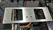
more photo notes, digging into front display board.

face-1.jpg
still looks good even without the face plate.

face-2.jpg
although this is one really thick chunk of metal.

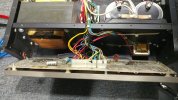
face-3.jpg
relatively easy to deal with wire harness connections. unlike some brands that have an unusual addiction to delicate wire wraps.

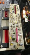
face-4.jpg
axial electrolytics used throughout the face board, both sides. delicate plated through-hole, easy to overheat and delaminate.

face-5.jpg
look at all the caps to replace, a little over 2 dozen for both sides. should massage the chips in their sockets in case of oxidation over the years.

face-6.jpg
chips and nice solder flow on the components.

face-7.jpg
another chip number for future reference, rc4558 is an opamp also used on the amp pcb.


interesting how much like the 700 Series II it looks like from the front, yet has a completely different meter board setup.
 
more notes and measurements.

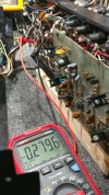
hi-z-1.jpg
voltage drop across r126, 104.3vdc which equates to high heat generation.

hi-z-2.jpg
high-z mode for the voltage shown above with the dc bias measuring around 280mv. service manual calls for between 0.3 and 0.4v (wide range).

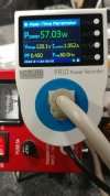
hi-z-3.jpg
numbers at idle, no dim bulb(*), high-z mode. interesting to see constant high current being controlled by low power factor.

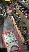
lo-z-1.jpg
low-z dc bias around 180mv, i did not think to measure r126 voltage drop for comparison... nuts.

lo-z-2.jpg
low-z idle at bias measured above. current dropped a little and power factor went down significantly.

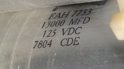
pwr cap 77mm x 145mm 13000_125v.jpg
power filter cap info, ~77mm diameter by ~145mm tall not including a few mm extra height for screw terminals. 13000 x2 seems a bit anorexic, looks like diane needs a few more millifarads on the frame to help bench press low efficiency speakers into sub-orbital altitude. also shou;d figure out a soft start since inrush, when the caps are flat, is quite high especially since it now wipes out the variac 5a fuse on power up. hello variable mains power up (variac for the win).

(*)dim bulb note: after setting each channel bias to 160mv (on dim bulb) it was no longer possible to boot up the amp on dim bulb (40+40 parallel = 75w usable restriction/safety net = saved my a$$ more than a few times). even when going from my usual 40+40 candelabra to 100w standard size bulb. power supply rails were not reaching the minimum needed to click any of the relays. so the amp went off the wattage choke chain and wandered freely around the yard for the first time (organic free range amplifier). obviously higher dc bias means higher idle wattage but we will get there eventually.

when the bias pots were replaced also changed r122/r212 from 820 (schematic and pcb) up to 1k 1w 0.1% to help with bias stability at high temps.

the 15v zener measurements are of some concern (d101/d114). i should consider replacing the pots on the display board as well.

will post more info soon.
 
This is all fantastic! Thanks for posting all of this and including the pictures. Organic free range amplifier,.... I love it! You forgot 'Non GMO',.... :cool:
 
You forgot 'Non GMO'
typically class-a and class-b amplifiers are non gmo since monsanto hasnt figured out their genetic sequencing yet. its the class-a/b amps that are more susceptible to crispr mods that make them more tolerant of using roundup. which in turn increases auditory canal inflammation which is the leading cause of selective hearing when in earshot of the spouse.

apparently a heavy metal guitar riff supplement helps clear things up provided the dosage amplitude is correct i.e. live ozzy concert or high dynamics techno like infected mushroom.

www.statnews.com/2016/09/22/monsanto-licenses-crispr/ [poisoning the world as usual]

www.youtube.com/watch?v=A_xC2mFGDzQ [metal compilation]

www.youtube.com/watch?v=D8gHFd1Slfo [electronica compilation] nice channel variety.

www.youtube.com/watch?v=1NfjSmnOOxA&list=PL1yLepH6zenKxr_AVRkK3P-WUD7eMwUKE&index=11 [if you want to blow up speakers+amps]
 
a few things i bumped into on other websites:

Screenshot 2023-08-02 at 10-47-37 Audiogon Discussion Forum.png
.
Screenshot 2023-08-02 at 10-47-53 Audiogon Discussion Forum.png
.
Screenshot 2023-08-02 at 11-03-19 Class B Power Amplifiers.png
.
basic info about amp design and what others have noticed. biggest concern is avoiding a 36 gun salute when demo'ing the amp. the cooling fan is configured for 58c activation which seems a bit high. also need to evaluate air flow especially through the thick metal screens covering the output transistors. i see thermal sandwich potential which not a good thing. extended testing will be needed, hello thermal camera.

the webpage screen shots were achieved using lightshot (screenshot tool) add-on for waterfox/firefox.

*crossover distortion seems like a misleading way of describing transition dead zone (zero cross), when output signal hangs out at 0v a little too long. for 3ph ac motor controllers its called dead-time (a necessity) although pwm motors controls are a completely different topology. the joys of 1600v 1000a rated igbt's and how not to blow them up.

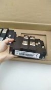
holding igbt.jpg
size comparison of igbt vs human hand. makes hifi transistors seem like grains of sand doesnt it.
 
there are a lot of odd terms in electronics that may not be the most accurate. Guessing "crossover distortion" came from the idea that the signal was "crossing over" the zero line. So long as everyone understands what you mean I guess its not a problem though.

The harmonics you get from that are nasty either way. Every 3 phase motor on a VFD I've ever heard makes whining noises that change based on frequency and load.


Is the fan controlled by that temperature switch screwed to the heat sink? If so it would be nothing to change that to a lower temp switch. Or maybe convert it to a DC fan and mount a thermistor back there. Knock together a voltage reg circuit controlled by the thermistor so the fan speed varies as required in order to maintain stable temperature, not just an on/off switch that kicks on once it gets good and hot.
 
Every 3 phase motor on a VFD I've ever heard makes whining noises
sounds like a low carrier frequency vfd in the human hearing spectrum whether it be 1k/5k/8k/10khz. the vfd company i helped manufacture and repair drives for were designed for 20khz or higher carrier which was far less of an osha hazard. it always felt weird to power up a repair unit dripping with machine shop oil (thick atmosphere) with 480 knowing that things could go horribly wrong with the 650vdc bus rails staring me in the face.

Is the fan controlled by that temperature switch screwed to the heat sink?
looks like there are at least 3 large round heat sink temp monitoring devices not including the thermal feedback transistors for the bias circuit. somewhere i read that the fan blows outward/away from the output transistors but i cant find where. a quick inspection of the fans side housing should have some rotation and flow arrows to solve my confusion.

one redesign idea i am kicking around involves heat reduction for the 3k 5w resistor area. one thought process is to use 60v 5w zener regulator down stream of a 1.5k 3w connected to the b+ or b- voltage (1 mod each rail). +voltage rail from power cap >> 1.5k 3w >> 60v 5w zener cathode >> 15v zener cathode (normal circuit regulator). although one concern is the delayed ramp up of the ic chips circuit particularly involving predriver/driver/outputs and the various safety circuits.

another idea would be to use dc-dc converter that can handle high dc voltage from the source rail, eliminating 3k resistors completely and dialing it in for either +15 or -15 (2 separate modules) which would also eliminate the 15v stock zeners. there is some concern about the dc-dc switching frequency dumping noise up or down stream (ferrite beads would help mop things up a bit).

but then again i am making something simple far more complicated than it needs to be... in the name of less heat/energy waste.
 
feeding a zener to get a 15v supply?
correct, zener regulators for the +/- power for most of the chips. not sure if there is anything else tapping the low voltage, schematic is blurry in various areas. vintage gear loves zeners and dropping bulk voltage down with resistors to something that wont blow up the zener(s), just cooking the zeners though. seen back light circuits that cooked themselves to death, luxman comes to mind.
 
haven't really studied this too close but it appears there are two voltage taps on the output transformer and it switches between them. Says the rails are either +/- 85 or +/- 120. Looks like the 15v supply must be derived on the board from whichever one is active at any given time. Not sure what does the switching here but if its mostly in high voltage mode, maybe knock together a power supply fed from the low voltage terminals and feed those resistors from that. Would drop the input voltage by 35 volts, which ought to reduce the heat produced in those resistors. Would come at the cost of an extra bridge and pair of filter caps though.
 
after doing a circuit sim with the large zener idea the overall wattage consumed is higher than the stock design. so much for that idea.

Not sure what does the switching here
the 120vdc to 85vdc is controlled by the front panel hi-z/lo-z switch. plus there is a detection circuit if distortion is detected in hi-z mode, it will automatically drop to lo-z.

a few things in the service manual that are interesting to note:

117v - service manual - Phase Linear Dual 500 Series 2.pdf.png
this hungry monster amplifier prefers a 20a circuit, looking forward to measuring the inrush with my scope. 117v mains might be the ideal voltage to apply which would make 120v (the residential "norm") slightly over-voltage condition. need to measure rails at various mains voltages to evaluate further. power filter caps rated for 125v and it would not be too difficult to exceed that.

1800w - service manual - Phase Linear Dual 500 Series 2.pdf.png
15 amp mains fuse obvious is a safety restriction but it also will not allow the amp to function to its max "rated" output, if the above is accurate. although 120v * 15a = 1800w assuming power factor of 1. if it takes 1800w to produce 1010w stereo for audio purposes that would be 56.11% efficiency. still better than pure class-a but the electric bill is going to rise depending on long term volume levels exercised.

bias - service manual - Phase Linear Dual 500 Series 2.pdf.png
highlighting the bias range which is quite wide. although if hi-z is set around 380mv and lo-z measures somewhere above 300mv that would fit perfectly.

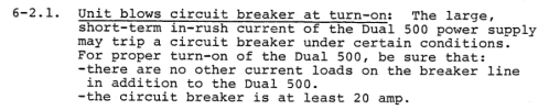
breaker - service manual - Phase Linear Dual 500 Series 2.pdf.png
"may trip", more like it will trip since there is a high probability of other devices being on the same mains circuit that are actively consuming power. how many households in the late 70's had a dedicated 20a breaker or circular fuse to handle such an unrestricted inrush. whole home brown-out when turning the amp on after letting it completely discharge.

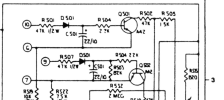
d502 - Phase Linear Dual 500 Series 2 Schematics.pdf.png
will the real d501 please stand up. diode 502 where are you?

speaker - service manual - Phase Linear Dual 500 Series 2.pdf.png
sentence #1 says it all, i wonder how many consumers realized this after the woofer related fire transpired (attendance of beer optional)?

spec - service manual - Phase Linear Dual 500 Series 2.pdf.png
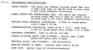
pretty beefy specifications for the late 70's, wonder how many woofer repairs resulted after the dual 500 was unleashed. the infrasonic safety circuit may indicate that this would not be an ideal subwoofer amp, results may vary. although class-d these days pretty much steals the show, local demo's of some b&o ice amps have revealed much. 20v/us minimum seems adequate although unimpressive as far as high numbers/spec marketing goes. if its above 1.2v/us it will be good enough for 20-20k spectrum, not exactly a high bar to overcome.
 
would destroy most anything connected to it - hardly the amp's fault.
very true on both counts. finding hifi/decent speakers that can handle brute force amperage is a difficult task. i wonder if this amp would light up a pair of polk sda srs favorably i.e. no calling the fire department? learning amplitude restraint typically happens "after" the woofer cones are on the floor behind you. then the usual yelling and screaming about the speakers costing 7-10k, such a mood killer.


demo-1.jpg
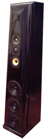
too many toys in the test chamber. thiel cs5 obviously in front of the polk's.

 
Back
Top Bottom