• The move to the new server is done. There are some software and database maintenance updates in process. This has us passing the hat around to help out. We appreciate any donations. Seriously, even a dollar helps. The payment page may be found here - https://www.audiokarma.org/support.html

Pilot 240 motorboating

Man! That seems more than simple "motorboating" I've experienced in amps. What I'm used to, is around 4:40 of this video. A much slower putt-putt rate.


In any event, definitely some crazy oscillation issue. Have you tried pulling tubes in the gain stages, one-by-one, to see if you can isolate that noise to one stage? If you find one stage that has the biggest effect on the noise, try the extra cap across that stage's tap from the power supply. You may need to try different tubes or even check all the wiring layout in that stage.
 
Yeah the noise is crazy! I couldnt think of any better way to describe it though. Its been super hard to diagnose because itll disappear for months at a time then come back for a few days. Its slowly gotten worse overtime and now it almost alwaysgoes crazy like that when i turn it on. I havnt done too much experimenting while it was powered on and screaming because it does it at full volume and drives me nuts haha.

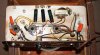
As far as wiring layout, the can caps have been replaced with components under the chasis. Do you think changing the layout like that could cause something like this?
 
Yeah the noise is crazy! I couldnt think of any better way to describe it though. Its been super hard to diagnose because itll disappear for months at a time then come back for a few days. Its slowly gotten worse overtime and now it almost alwaysgoes crazy like that when i turn it on. I havnt done too much experimenting while it was powered on and screaming because it does it at full volume and drives me nuts haha.

As far as wiring layout, the can caps have been replaced with components under the chasis. Do you think changing the layout like that could cause something like this?

It's prolly a positive feedback issue. Power supply filtering and wiring layout are usual suspects. Oscillations induce from poor isolation of PSU stages and/or picking up ultra-high frequency instabilities from layout. Unfortunately, your amp has pure point-to-point wiring. So, finding the culprit(s) could be difficult. Isolation of the stage (by pulling tubes or using a scope), will cut down time spent searching. Adding a parallel cap to each PSU stage, one-by-one, is another shortcut way to find where the problem lies. Once you find the stage, THEN looking at the soldering, the wiring layout, each component's integrity will be an easier task.

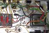
You know from this photo below, how the resistors & caps are soldered to the sockets are not really the best. They should have the shortest lead onto the socket side. This is because lead length capacitance (no matter how small) can contribute to instabilities. I've been taught to try to solder screen and grid stopper resistors across unused socket tangs, in order to keep the leads to the minimum. If not possible, keep lead at socket side as short as possible. :idea:


Good luck! :thumbsup: :)

index.php


------

Examples.

Grid stopper and screen resistors - AB763 mod.jpg chassis bottom.jpg
 
Last edited:
Any chance the output transformer leads have been disconnected from the output tubes and re-connected incorrectly? Is the appropriate speaker terminal properly grounded? Some grounded the 0 or common lead, others grounded the 4 ohm lead, so confirm on the schematic what it has to say. If thats not grounded properly the feedback circuit will act very stupid.

Looks like Pilot used the same sort of physical layout on this as they did on my SA-260, the tubes all in a line. I'm not a fan of that just because the run from the back tube to the phase inverter in the front of the line requires some long leads. It gets messy.
 
oh, one other thought, if the coupling caps between the output tubes and the driver got switched, it will do exactly the same thing.
 
Any chance the output transformer leads have been disconnected from the output tubes and re-connected incorrectly? Is the appropriate speaker terminal properly grounded? Some grounded the 0 or common lead, others grounded the 4 ohm lead, so confirm on the schematic what it has to say. If thats not grounded properly the feedback circuit will act very stupid. phase inverter in the front of the line requires some long leads.

Also, if the feedback loop got re-connected to the wrong half of long-tailed style phase inverter. :idea:
 
I think Pilot ran a paraphase inverter but I didn't look at the schematic. Would do it there too though
 
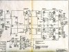
Partial schematics I found on Net.

Pilot 240 schematic (2).jpg

The 150mmfd/6500-ohm(?) global feedback network may have a defective cap or have been miss-wired. And now is out-of-phase with the phase inverter half where it is attached.

Try temporarily removing this GNFB network and see if the noise goes away. :idea:
 
Thabks for all the responses guys! Sorry, ive been super busy today pricing out albums for my shop but im going to sit down with the amp tomorrow and see what i can figure out. On the global feedback network, i dont really know how to read a schematic yet. Most of what ive learned has been through the site here. Ive successfully completed 4 tube amp restorations thanks to the info i found here but unfortunately ive hit a snag with this one. If i post some good pics could you walk me through how to remove the GNFB network?
 
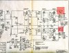
GNFB networks for each channel are highlighted in red. Very hard to make out exact values. You will see a line coming from the speaker output terminal. Back to the 12AX7 phase inverter. This is prolly the GNFB line. A closer photo of this area of the amp and the wiring off the speaker terminals with any attached disc cap and resistor will help.

Pilot 240 schematic (2) GNFB network.jpg
 
Last edited:
It looks like it says150mmf but i don't think theres any caps that size in my circuit. Is that schematic for the pilot 240?
 
usa_pilot_240_sch1b.png Thatsweird, ill have to double check when i get it opened up. Heres the schematic ive been working with.
 
I tried to sign up there years ago. The Little Orphan Annie decoder ring got lost somewhere in the mail from Belgium or wherever it comes from. Never have gotten it to work and I gave up a long time ago. I'm a registered member but not confirmed, and I can't get the confirmation to work.
 
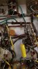
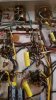
Ah bummer. Well im lookin atthe amp now and im seeing some discrepancies. So the yellow wires in this pic each come from the speaker outputs for either side but when they conenct to the gloabl feedback network each side is different. Channel A has the speaker tap connected to a 10k resistor and 150mmf ceramic cap in parallel. Channel b is running to a cap that says 250mmf and the resistor its parallel with is 4.7k ohms. Channel b seems to be were the sound is coming from.
 
Back
Top Bottom