• The move to the new server is done. There are some software and database maintenance updates in process. This has us passing the hat around to help out. We appreciate any donations. Seriously, even a dollar helps. The payment page may be found here - https://www.audiokarma.org/support.html

Pioneer SA-7500 (not mkii) won't kick relay out of protection

I did start probing around to see incorrect voltages on the main amp. I'm not really sure what goes where so it's a bit like prom night. But here are some things I found.
Q1-4 on the power amp have 14vdc on the base. It should be very low or zero.
Q7 has 33vdc.
Pin 10: zero volts, should be -13
VR3 and 4 are 2.5 and 1.4, should be around .15.

Let me know if there's some other intel I should be getting.
 
Just checking in. I'm getting good voltages from the PS but very high DC offset at pins 3 and 17 (should be 0v and it's 30 and 35 vdc).

Any place I should investigate? I know Q1-4 has the dreaded 2SA726 transistors and Q5-6 are QSC1451. Could this area be where my problem lies?7500 power amp.jpg
 
Just checking in. I'm getting good voltages from the PS but very high DC offset at pins 3 and 17 (should be 0v and it's 30 and 35 vdc).

Any place I should investigate? I know Q1-4 has the dreaded 2SA726 transistors and Q5-6 are QSC1451. Could this area be where my problem lies?
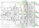
Did you confirm the power supply voltages (green boxes) at the amp board?

If the incoming voltages are OK then check the yellow box voltages.

7500amp.jpg
 
I think all but Pin 10 in green is OK. I get zero at Pin 10.
You need to go back to the power supply and confirm that pin 21 has -13 volts. If it does then trace the wire to the amp board. If it does not the power supply has a problem.
 
You need to go back to the power supply and confirm that pin 21 has -13 volts. If it does then trace the wire to the amp board. If it does not the power supply has a problem.
My bad. I must have measured that wrong. Confirmed -13 on Pin 10. All in green are good.

Most in yellow are bad.

C9-10+: 35 (should be 24.3)
Q5 (BCE): 0, 30, -40 (b should be -38.8)
Q6: B: -40 (correct, I think)
Q7: B: 33 (should be 1.2)
Q8: B: -36
Q9: B: 31 (should be -1.2)
 
@mrk229 et al, any next steps?

I also know I don't have the KSC3503 subs for 2SC1451 but HKer Ben has them around. I do have KSC2690AYS, which seem like a nice match. Should I order a couple 3503s to get those 726s out of there at some point?
 
Waiting on 1451 transistors so I pulled Q1-4 on power amp. They’re supposed to be matched pairs, correct? In any case, Q1 had a gain of 4 and Q2 was 420 (hfe). Q4 was a different transistor altogether and also had low gain, 9.

Still not past protection. I’ll check Q5-6 next unless there’s something more pressing. I’ll also get new data on voltages.
Not good. Did you replace Q1 through Q4 and still have protection issue? They should be a closely matched as you can get. If you did replace them have you looked at the offset voltages?
 
Not good. Did you replace Q1 through Q4 and still have protection issue? They should be a closely matched as you can get. If you did replace them have you looked at the offset voltages?
Correct. Replaced all four and still in protection. I’ll check voltages. The DC offset was very high (30. 35v) so I’m thinking it’s something worse than non matched pairs. I did match these to around 430 hfe.
 
You are probably correct if the offset is that high. Is the high offset on both channels?
Interesting. The Q1-4 replacement fixed offset and bias. I can easily dial both in.

Still in protection. I think next I need to pull and replace Q5-6 or retest main amp voltages in yellow above?
 
Interesting. The Q1-4 replacement fixed offset and bias. I can easily dial both in.

Still in protection. I think next I need to pull and replace Q5-6 or retest main amp voltages in yellow above?
Please explain
Q1-4 replacement fixed offset and bias. I can easily dial both in.
I thought you had already replaced them and had 30 & 35 volts?

If indeed the bias and offset are OK then the problem would have to be in the protection circuit.

Just so we are on the same page where are you measuring offset? Pictures are one of the best ways to understand.

Or there is the: :needpics: Have not used it in a while.
Not worthless but extremely helpful.
 
Please explain

I thought you had already replaced them and had 30 & 35 volts?

If indeed the bias and offset are OK then the problem would have to be in the protection circuit.

Just so we are on the same page where are you measuring offset? Pictures are one of the best ways to understand.

Or there is the: :needpics: Have not used it in a while.
Not worthless but extremely helpful.
No I had high offset and low bias that was fixed after replacing Q1-4 on the main amp.

I’m measuring pins 1 and 2 for the bias of one channel and 18, 19 for the other. Pins 3 to ground and 17 to ground for DC offset. I can snap some pics!
 
No I had high offset and low bias that was fixed after replacing Q1-4 on the main amp.

I’m measuring pins 1 and 2 for the bias of one channel and 18, 19 for the other. Pins 3 to ground and 17 to ground for DC offset. I can snap some pics!
Sounds exactly right. We probably need to move on into the protection circuit.
 
Sounds exactly right. We probably need to move on into the protection circuit.
Edit: I realize I already replaced Q5-8 on the switch circuit assembly with KSC1845F. Next steps are to probe for voltages with what's listed in the service manual?
 
Last edited:
There are three triggers for the protection circuit. Those are summed with the diodes at the right edge of the left outlined block with Q14, Q16 & Q17.

The circuit requires three voltages to be present to work. AC voltage which is rectified to -5.1 volts. -13 volts and the +35 volts. Look for those first.


7500protblk.jpg
Blue is the AC input. Green is the -5.1 volts. Red is the -13 volts and the yellow line is the +35 volts.

7500prota.jpg
 
Back
Top Bottom