I think it looks pretty good. C21 is a bit low. All taken on a 30w dbt. C21 jumps to 3v using a 75w bulb on the dbt.There are three triggers for the protection circuit. Those are summed with the diodes at the right edge of the left outlined block with Q14, Q16 & Q17.
The circuit requires three voltages to be present to work. AC voltage which is rectified to -5.1 volts. -13 volts and the +35 volts. Look for those first.
View attachment 3494536
Blue is the AC input. Green is the -5.1 volts. Red is the -13 volts and the yellow line is the +35 volts.
View attachment 3494537


You are using an out of date browser. It may not display this or other websites correctly.
You should upgrade or use an alternative browser.
You should upgrade or use an alternative browser.
Pioneer SA-7500 (not mkii) won't kick relay out of protection
- Thread starter da_kube
- Start date


OK we have power.I think it looks pretty good. C21 is a bit low. All taken on a 30w dbt. C21 jumps to 3v using a 75w bulb on the dbt.
Check the voltage at the base of Q9. That is the trigger point from the detector steering diodes.
Check R45.
Confirm the voltage at the collector of Q11 it will be near 35 volts if the relay coil is good.
The 8.3 volts shown on the C of Q11 would be that value with the relay closed.
If those are all good pull Q10 and see if the relay closes. That will tell us if Q11 and the relay are OK.
While you have Q10 out go ahead and test it.
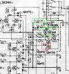
For this, do I just measure resistance across in circuit with the power off?Check R45.
Ohh, we got clues!OK we have power.
Check the voltage at the base of Q9. That is the trigger point from the detector steering diodes.
Check R45.
Confirm the voltage at the collector of Q11 it will be near 35 volts if the relay coil is good.
The 8.3 volts shown on the C of Q11 would be that value with the relay closed.
If those are all good pull Q10 and see if the relay closes. That will tell us if Q11 and the relay are OK.
While you have Q10 out go ahead and test it.
View attachment 3494633
Q9 (BCE): 6.2, .7, 6.8 (not good?)
Q10: .7, 6.8mv, 0
Q11: 7mv, 34v, 4mv (relay coil is good.)
R45: 220 ohm across in circuit.
Last edited:
Done. It does not.Lift one end of D17 and see if the relay closes.
In that case lift one end of D15 and D16. Those are the DC offset detection circuit. D17 was the amplifier overload/overcurrent detection circuit.Done. It does not.
Got it. I leave D17 out for the time being? And should I do D15, test, then do D17 or take both out of circuit?In that case lift one end of D15 and D16. Those are the DC offset detection circuit. D17 was the amplifier overload/overcurrent detection circuit.
It clicks!Leave D17 out and lift both of the others. That will remove all triggers and the relay should pull in if the rest of the circuit is working.
 Now we need to find the fault. Pop D17 back in and confirm it still works. If so the problem is in the offset detection circuit. I believe you checked and set the DC offsets at the pins on the amplifier board correct? If that is the case then pull and check Q7 and Q8.
This makes sense. One thing I meant to do was check my work after replacing Q5-8 and I see I put Q8 in wrong.
I think I put D17 back and test on DBT, then fix Q8, then put D15-16 back?
If bias and offset have been OK there is no need for the DBT at this point. Diff amps don't diff too well if the transistor is in wrongThis makes sense. One thing I meant to do was check my work after replacing Q5-8 and I see I put Q8 in wrong.
I think I put D17 back and test on DBT, then fix Q8, then put D15-16 back?

Put D17 back check for relay working. Fix Q8 and put D15 & 16 back and test again.
Last edited:
Yea I’m usually more careful but that was a pita to slide in there. Any chance I did no damage?If bias and offset have been OK there is no need for the DBT at this point. Diff amps don't diff too well if the transistor is in wrong
Put D17 back check for relay working. Fix Q8 and put D15 7 16 back and test again.
Pretty good chance you did no damage. We have all done it at one time or another.Yea I’m usually more careful but that was a pita to slide in there. Any chance I did no damage?
Last edited:
You are correct. The diff amps work quite well when installed correctly. All is well and this amp is singing again. Thanks so much for your help and detailed explanation of things. I learned a lot on this one.If bias and offset have been OK there is no need for the DBT at this point. Diff amps don't diff too well if the transistor is in wrong
Put D17 back check for relay working. Fix Q8 and put D15 7 16 back and test again.
One issue remains and I can start a new thread if preferred: This came with all four top case screws missing and I’ve had a pita of a time finding some that fit. They’re M4x8 and NOT .7 pitch. Does anyone know what pitch screws were from this amp? I maybe just need to buy from the Bay because it’s hard finding anything that’s not .7.

congrats!All is well and this amp is singing again.
So I replaced the main filter caps and rectifier diodes on the power supply. I've replaced Q5-8 on the protection circuit and the four 2SA726 differential pair transistors on the bias circuit for the main amp. I plan to replace the four VR resistors on that amp and also do the caps.
Other than that, are there any things I should preventively do? I plan to do the 2SC1451 (Q5-6) on the main amp board as per Mark the Fixer's suggestion. I also plan to install the flyback diode on the relay that he suggests here (since the part is handy). Does the attached image show the correct way to do it? Anything else I should to preventatively?
Thanks all for the help with this!
Attachments

Yes that looks like the correct way to install the diode.So I replaced the main filter caps and rectifier diodes on the power supply. I've replaced Q5-8 on the protection circuit and the four 2SA726 differential pair transistors on the bias circuit for the main amp. I plan to replace the four VR resistors on that amp and also do the caps.
Other than that, are there any things I should preventively do? I plan to do the 2SC1451 (Q5-6) on the main amp board as per Mark the Fixer's suggestion. I also plan to install the flyback diode on the relay that he suggests here (since the part is handy). Does the attached image show the correct way to do it? Anything else I should to preventatively?
Thanks all for the help with this!
Almost every transistor on the EQ amp and control amp board is on the top ten troublesome transistors list.
Geez, you weren't kidding. 10 on the two boards.Yes that looks like the correct way to install the diode.
Almost every transistor on the EQ amp and control amp board is on the top ten troublesome transistors list.
For reference, if anyone needs this info: 2sc1312 and 2sc1313 are NPN get subbed with ksc1845 and 2sa725 and 2sa726 are PNP and get subbed with ksa992.