• Please note that Audiokarma will be offline briefly for updates early on Monday morning, September 28th.

PIONEER SX-440 Output Transistor Replacement?

I also have noticed that @merlynski has been missing,
I miss reading his excellent detailed explanations.
Really hoping he's ok! There are extremely generous helpful people on this forum.
 
Update: Still have significant distortion issues across both channels, hoping one of you can point me in the right direction.

Status/Conditions:
  • Most all caps and all transistors replaced on audio board - pin outs double checked, most caps had drifted up roughly 20%
  • All pots and switches cleaned thoroughly
  • PS transistors, caps and zener diode replaced
    • PS voltages:
      • 1) 11.59V DC
      • 2) 41.14V DC
      • 3) 26.36V DC
      • 4) 29.9V AC
      • 6) 29.8V AC
      • 4-6) 59.3V AC
  • Found R6-9 resistors were not in good shape, brittle and green at junctions, replaced all four
  • Output transistors pulled and tested close enough to spec, no shorts
    • Case voltages
      • Q3 18.71V DC
      • Q1 41.10V DC
      • Q4 19.12V DC
      • Q2 41.09V DC
  • Bias is a bugger to get down to acceptable reading, I have to crank both VR's hard CCW, almost pegged, to get down in the 10-15mV range
  • Running through DBT during testing
  • Distortion is across both channels running through speakers but isn't nearly as significant via headphones
What am I missing here? Feels like since it's both channels it's got to be PS but other than the three remaining big caps I've replaced nearly everything else and/or determined they're not faulty. Feels like I'm so close!

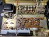
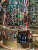
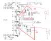
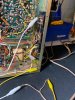
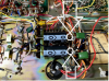
IMG_0551.jpg IMG_0552.jpg IMG_0553.jpg
 
The outputs to the speakers run through the headphone jack, try bypassing that switch (clip jumpers?)
also there are fuses (old?) that can be getting on in age and while conducting, doing a poor job of it.
again clip jumper bypass temporarily.


New transistors (lower Vbe's) except outputs, idle current high... figures...
idle current.. R356 & R357 4.7k, try a 5.6k and see...

more resistance reduces STV-3 current and thus voltage across it, reducing idle.

CAREFUL - OPEN CIRCUIT @ THERMAL DIODE = BLOOIE!!!!!
 
Last edited:
  • Like
Reactions: JB8
Thanks, Mark, really appreciate the advice here, now I just need to wait for the 5.6k's to arrive - one of the only values I didn't have in my box of resistors...

I'll update once I have them installed, thanks again!
 
Quick update, 5.6K resistors arrived and have been installed but I'm wondering if I purchased the wrong ones (pictured)? Sounds like there's more of a ground hum now, and if I wave my hand under the audio unit section I get a considerable amount of hum, which I don't remember being an issue before. I was able to set the idle and get the voltage at the speaker terminals down to less than a volt DC but they still seem a bit high, maybe I have poorly unmatched hFE's on some of the new transistors I installed. I had higher than desires voltage at the speaker terminals on another unit I'm also working on and once I matched the hFE's it made a huge difference. Dumb question, but which are the pairs that need to have matched hFE's on this SX-440?

I'm still going to check out the fuse scenario as well, there's at least one very old one that I haven't changed out.

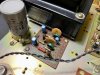
IMG_0740.jpg
 
Well, there's no color codes to misread there. An ohmmeter reading would tell.

A lot of units get hum when open on the bench. Putting on the top and bottom plates usually cures it.

Does it have a metal or wood case?
 
Hey Mark, I think the lack of color codes was what got me spooked, they test out fine.

Wood top, metal bottom, I'll get it buttoned up and do some additional listening/testing, thanks again!
 
I replaced the 3A fuse on the underside of the unit after swapping out R356/R357 with 5.6K ohm resistors, still getting massive distortion through the speakers, sounds fine via headphones.

I also jumpered into the headphone jack to hook up a speaker and got distortion there as well. Also getting considerable hum if I get my wooden probe anywhere near C327/C328 - both had been replaced (w/3.3uf 50v) making sure the polarity was accurate. May not be contributing to the issue but still wanted to report it.

While most of the caps have been replaced on the audio unit there are still several of the 3.3uf that remain original along with the main filter caps and all caps on the FM board.

The distortion is happening across all function and kicks in at fairly early when turning up the volume.

If, with volume at zero, I switch through the functions, the buzz/hum is the same for the AM/PHONO/AUX settings, but slightly louder and higher frequency when in FM stereo or FM. When I reinstalled the metal base plate the buzz/hum was still there. I'm far less concerned about the hum at this point, again, just part of the diagnosis.

Any suggestions would be awesome. I'm entangled with several units right now, staying the course on all of them in spite of all the dead ends, keeping hope alive, ha!
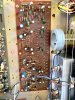

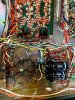
IMG_0741.jpg
 
Are the "but other than the three remaining big caps" still in there?

One I see in the pictures, 1000uF 50v chassis mounted
two I do not, 1000uF, 25v.

There is one main filter cap, 1000uF 50v.....

Those two 1000uf 25v caps are passing audio and they should be new.

plus the audio HAS to travel THROUGH the headphone jack. The fact that you report BOTH channels distorted is disturbing.

Try connecting the speakers to the INPUT side of each 2 amp output fuse. (minus side of c9 & C10)
See if that changes anything - without the fuse, headphone jack and all that other crap in the way.
EDIT: somehow I was misled about the fuse situation, there are POWER fuses for the amp in the schematic, there are no SPEAKER fuses IIAC...


If not, then start checking the transistors of the drivers and outputs - the emitter to base voltages.
also read the voltage on the + side of c9 & C10.
be prepared to list original and replacement part numbers.

and when units get tough, multiple opponent round robin chess is not the path to success.
this one fits in that category.
 
Last edited:
  • Like
Reactions: JB8
Thanks, Mark, this is now the only match I'm going to concentrate on until it's done, the others can wait, I appreciate your sage advice!

All three of the big caps you mentioned are original and I have replacements to swap in - specifically, I have a 1000uF 50V for the chassis mounted cap, and two 1000uF 50V axial's (C9/C10), assuming I should also replace the 100uF 10V little guy next to the axial's as well.

Once they're installed I'll test again, and if the issue still persists, I'll move on to the other tests, document along the way and report back with my findings.

Thanks again, Mark!

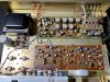
Some mid-point reference shots:

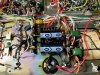
IMG_0752.jpg IMG_0753.jpg IMG_0754.jpg
 
Last edited:
ok, yes.

what we will be doing is seeing how well the halves of the push pull circuit are behaving.

before the coupling cap the output pin 7 (20v) should have about half of the pin 3 voltage (40).
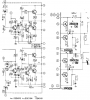
Check all the transistors in the diagram below for about 0.6v or so base to emitter.+ for PNP - for NPN


upload_2022-5-5_21-56-13.png
 
  • Like
Reactions: JB8
Update:
  • Main filter cap replaced with 1000uF 50v - old cap tested out of chassis at 1100uF
  • C9/C10 replaced with 1000uF 50v axial caps - old caps tested at ~1300uF and 1200uF
  • 100uF 10v cap (not sure what part number it is) replaced with 100uF 25v cap - old cap tested at 130uF
  • Case voltage matched output pins 7 and 3 at 18.5v and 40.5v respectively - actual case voltage is 40.5v DC for Q1/Q2, 17.7v for Q3, 18.7v for Q4
  • All transistors had been replaced on both the PS and Audio Unit:
    • Q101/102 2SC968 > 2SC2383
    • Q307/308 2SC870 > KSC1845
    • Q309-312 2SC734 > KSC1845
    • Q313/314 2SA561 > KSA1015
    • Tested B-E voltages and had consistent readings for all in the .675v range
    • No hFE matching performed before installing, potentially due to ignorance
  • Voltage at + side of C9/C10 is 18.01v and 17.64v
  • Tapped into headphone jack again, after the resistor - sounded fine. Jumpered in before the resistor, horrendous distortion.
I briefly checked the idle current, it was in the 14-16mv range, voltage at speaker terminals is now at ~.5v where before the cap swap it was closer to 1v at start up.

Happy to try jumpering in via the - side of minus side of C9/C10 but I'm not exactly sure where to locate the +/- speaker leads. I know where the neg. side of the caps are but not sure where the pos. clips need to go.

I know we can solve this, as time permits, let me know what next steps I should take.

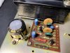
IMG_0759.jpg IMG_0761.jpg
 
Well, the positive side of the speaker caps (C9 & C10) have 20v or so on them, and is precisely what those capacitors are blocking. Never go to the + side of the cap and directly to a speaker. Also if the cap is in backwards, it will just act as a short circuit and the speakers will be destroyed.

When you have a sounds bad situation, read the pin 3 voltage, see if the voltage is
being pulled down by the amplifier load.

Are you using the same speakers in good & bad? If so, in bad it's a LOT quieter, right?
It's also less of a load.

upload_2022-5-6_17-44-54.png
 
Pin 3 is starting at 41.83v and being pulled down to roughly 41.50v under load, so it's definitely being pulled down some. And yes, using the same speaker for good and bad, and when it's bad it's a lot quieter. Through headphones it seems to sound fine but of course you can't really crank it up too far.

I'm testing by using the two #3 pins in the pic and have my test speaker hooked up via the pos. (top lug) of the speaker out then grounding to the chassis.

IMG_0763.jpg IMG_0764.jpg
 
no no no pin 3 does NOT get the speaker, it is your voltage monitoring spot!!!


what is the dc resistance of your speaker?
 
Don't worry, only using the #3 pins to test voltages, I'm using the speaker lug for the actual speaker. First pic is test points, second pic is speaker hook-up.

The test speakers are these little Sony's, I think they're from a surround sound system, little cubes. DC resistance is 6.2 ohms when testing at speaker cable ends. The label on the speaker states they're 6 ohms.
 
Ok, i see it now.

Take the white alligator clip and connect it to C9 negative (or C10 negative).
The side with the green part near it. Leave everything else the same.

6 ohms may be too low of a resistance, do you have some 2 ohm to 10 ohm resistors?
otherwise if there are two speakers, put two of them in series for 12 ohms and see if that
clears up the distortion.

That would explain when on the far side of the resistor it sounds fine.

We have 2 potential sources of distortion right now:
6 ohms instead of 8 ohm speakers
the possibly bad contacts in two switches : S3: speaker on/off and S7: speaker a / speaker b

upload_2022-5-6_19-18-6.png
 
oh well, the spec says 4 to 16 ohms...

I'm looking for pin 3 voltage dropping 10 to 20 volts when distorting.
 
Back
Top Bottom