• The move to the new server is done. There are some software and database maintenance updates in process. This has us passing the hat around to help out. We appreciate any donations. Seriously, even a dollar helps. The payment page may be found here - https://www.audiokarma.org/support.html

PIONEER SX-440 Output Transistor Replacement?

Yep, even with including a 5 ohm resistor it's still distorting when tapping into the negative side of C9. I'd also run through some JBL P20's and it was distorted through that set as well, and I know both sets of speakers sound fine when connected to other units.

Based on what we know so far specific to voltages, is there something in the PS that could be wonky, since the distortion is across both channels? Would be great if it was a component that was failing or was faulty when installed, but I'm clueless here.

Pretty strange stuff, totally stumped.
 
And thanks, Pete, I'll check out those solders, nice catch!

Update: It was just a strange angle, I touched them up but they were fine.
 
Last edited:
check the power supply

pin 2 42 volts power amp
pin 3 24.5 volts preamp including phono
pin 1 11.5v tuner
 
If you have another receiver with speaker, you can make a signal probe (fancy name for an rca cable with a non-polarized 0.1uf 100v cap connected in series to the center pin, probe with the other lead of the cap) and check the audio quality at various places in the unit.

Just get a ground to ground connection, another interconnect to a tape monitor for example - just so the RCA's shell is grounded on both receivers.
 
  • Like
Reactions: JB8
those voltages look OK, reread my posts, including the signal probe post.
 
  • Like
Reactions: JB8
I'm happy to build the probe but will need to score the .1uF cap, which isn't an issue.

When looking at a couple of video's on how to make these probes one dude said "these can be quite handy, especially if you don't have an oscilloscope"... Whelp, I have an oscilloscope with at least one good channel on it. I've used it before to look at signal at several test points on a unit that ended up having a bad transistor on the tone board, so if it would be easier to just bust out the scope I'd just need to know which test points to check out as well as what settings I'd need for the scope.

Feels like with the scope we should be able to rule out some of the boards and narrow in on the issue, I remain optimistic!

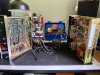
IMG_9959.jpgIMG_9950.jpeg IMG_9949.jpeg
 
Last edited:
not to knock the oscilloscope, but the audio probe makes it easy to distinguish distortion.
You can't SEE distortion on a regular audio signal, that requires a test tone.
Whereas any audio it will be as plain as day to your ears.

it's now been a considerable amount of time as I prepared stuff to POINT at using a test tone.
Then I stopped - you gotta GET a test tone, and I'm gonna have to teach you "scope".
and I'm fighting their service info. Their service information sucks worse than any others I have seen - and that's saying a lot.
it's a goddamn aggravating mess.

I ain't got that much time. Others might have and be willing to do all the typing.

Hours and hours for both of us with the scope, signal probe should be less than 1/2 hour - frankly 10 minutes.

Get it receiving and loud-speakering distorted FM audio. The power supplies were ok.

signal probe at the volume control, it is a convenient point between the tuner and the tone amp. probe the top and tap. tap goes to the tone amp. bottom is grounded.

probe the output from the tone amp / input of the power amp at the pin 2's with the 3.3uF electrolytic cap connected rather closely (about an inch?).

frankly, inside, there's the FM tuner, if it's got good audio at the volume control, great

next the tone amp - it's only ONE transistor per channel -
we can look at the input (volume control, and the output - the power amp's input)

finally the power amp. which we have been fighting with.

not all that much in there.
 
Last edited:
Thank you, Mark, I sincerely appreciate your time and effort here. I know you've likely got lots of other enthusiasts trying to learn these procedures as well, so I know your time is super valuable.

I'm certain I'll be able to utilize the test probe in the future, so I'll get cracking on building one and let you know how it goes, enjoy the rest of your weekend and thanks again!
 
Probe is built, I had an extra 3.3uf 50V BP cap, I hope that will suffice - I know you initially said .1uf 100V but then you mentioned just needing a spare BP cap, so I think I'm good to go. I included a ground clip in addition to your caution around grounding the two units via a separate RCA, which I'll do in addition to using the ground clip.

Just need to confirm if there are any components/test points on the audio unit I should stay away from? You called out the volume control, that seems pretty straight ahead, tone board #2 pins, makes sense. I just don't want to be indiscriminately probing and hit something I should stay away from.

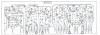
SX-440 Audio Unit.png IMG_0769.jpg

UPDATE:

Started testing, probe works great! Volume lead (green) was clear, no distortion. Both #2 pins were clear as well. Pretty low volume but clear.

IMG_0770.jpg
 
Last edited:
well, if both pins 2 (the power amp input) were clear, the power amp is at fault.

power amp is a system, internally the feedback system ties the parts together.
First there is the input amp that receives the input and the corrective feedback signal return.
A voltage divider here sets the gain. Gain is part of the correction.

then there is the voltage amplifier stage (VAS) which also makes the voltages to run the final stage.

The final stage is a current driver, the voltage stays the same, but the current capability is capable of driving 8 or 4 ohms.

There is a lot of things going on inside dynamically, it's the output that counts.
 
Thanks, Mark, feels like we're getting closer and I appreciate the explanation around the power amp system, definitely a lot for me to learn here.

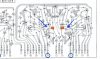
I've circled the test points I've been referring to, all of them seem pretty low in volume, I have to turn up both the SX-440 and the other receiver well past the mid point to get decent volume out of the speaker, but maybe that's to be expected based on my probe cap.

If the power amp is likely at fault are there other test points I should hit with the probe, and if not, what are the next steps? In the meantime I'll reread that last post of yours a few times and hopefully get it to sink in. Testing my zone of proximal development.

SX-440 Audio Unit.png
 
I have been trying to get back to continue that post.

what I was trying to say is that the input and output of the power amp can be probed for distortion, but the insides of the amp will have strange results.

both sides distorting seems like an error repeated for both channels. make SURE that all the listed resistor values ARE those values in the chassis, especially those connected to an output transistor. A legacy error - not done by you. TRUST NOTHING.

only around the 6 transistors per channel that are the power amp.

like a 22 ohm resistor being far more than 22 ohms, or a 220 being too high. or a 0.5 (one half an ohm) being too high. go by the schematic - not what's on the board (in this case)

I assume that all the e-caps in the amp are new?
 
Last edited:
Perfect, I'll dig in!

And yessir, all of the e-caps in the amp section are new.

Enjoy your evening!
 
In checking the power amp I only found one pair of resistors that were off with any significance.

R341/R342 are supposed to be 22K and tested at 14K/20K respectively. Both are inline with the bases of Q307/308, two of the new 1845's transistors. If the resistance is lower than spec, perhaps they're letting too much current through and overloading the transistor? When you talked about the interrelationship of the power amp components it got me thinking about the feedback conversations, etc, so maybe these are contributing to an imbalance once more signal is introduced due to reduced resistance? (this is me pretending I have a clue about this topic, ha!) My readings were with the resistors in-chassis, I'll pull one leg and properly test them in the morning before ordering any new ones or making any changes.

At any rate, I'd need to order up some of these, my resistor stock is feeble, I wish there was a multipack with the most commonly used values!

SX-440 Audio Unit.png

UPDATE:

Never mind, pulled one leg, did a proper test, both resistors tested fine... I'll keep looking.
 
Last edited:
Those are significant, they set base bias voltage
they are not in series, they form a voltage divider with 220k ohms to + supply.

Assuming 25v supply,
22k puts 2.273v
20k puts 2.083v
14k puts 1.496v
on the base of the transistor. I'm not sure about the emitter voltage and where it all comes from.
assuming a Vbe drop of 0.6v, it looks like there's 3mA flowing through 410 + 150 ohms.
The base circuit is probably at 100 microamps.

I'd have to do some digging to come up with an analysis of the design of that stage and that full power amp circuit.

I would say offhand, get the 22k in there.
 
Last edited:
Hey, I tagged on an update on my last post, I'd eventually pulled legs and tested as one should, the 22K's were fine.

I'll keep poking around but certainly feeling defeated by this one, feels like this is my first grapple with one that has no clear solve, no path to a fix even after replacing 50+ components, ha! Oh well.

Again, I appreciate your help here, I'll update the thread if something miraculous happens.

Btw, I'd already had a second unit on the way, glutton for punishment. It seems to work fine, no distortion, so I'm trying to study both and keeping hope alive!

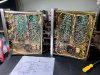
IMG_0781.jpg
 
Last edited:
Ok, ww mtf do?

edit:---------------------
In fact that point D 25v or whatever bears checking right now....
R343 is 6.8k ohms, hooked up to a 220 uF / 25v cap C341. See what voltage it is at now, it IS a common point between the channels.
Check that resistor for correct value. That whole part of the circuit was sitting in a kind of a blind spot.
---------------------------


I would get both running side by side as it were, and take voltage measurements on EVERY transistor (eb&c) including the outputs of both..
Then post the readings (for me to tear into, too) and compare them.
In the schematic, there is a power point that is fed off the 25v DC, denoted by the circled "D". Get that voltage too.
Because the amp is running off of both the raw DC 40v, and a conditioned (and perhaps strangled?) 25v.

In fact that point D 25v or whatever bears checking now....

R343 is 6.8k ohms, hooked up to a 220 uF cap C341. See what voltage it is at now, it IS a common point between the channels.

When replacing C341, bump up the voltage to at least 35v if not 50v.
 
C341 had been replaced, by me, with a 220uF/35v and the positive side, "D", is yielding 12.64v DC on the bad unit, 12.55v on the good unit. R343 tests at 6.8 in-chassis, I can pull a leg to confirm, but it seems to be fine.

I'll work on gathering the transistor voltage measurements across both audio units, so basically start with the 8 tripods on each board plus the output transistors and see what we get!
 
Last edited:
Back
Top Bottom