• The move to the new server is done. There are some software and database maintenance updates in process. This has us passing the hat around to help out. We appreciate any donations. Seriously, even a dollar helps. The payment page may be found here - https://www.audiokarma.org/support.html

Pioneer SX-980 Protection Relay Kicking Out

I have AFCIs in most of the living spaces, GFCIs in bath/kitchen/outdoor grade circuits, and plain thermo-magnetic breakers for utility areas without problems. I would suspect distribution power factor problems and/or locally generated noise from switching supplies before the breakers. Switching supplies without inductors are pure evil, like Google.
 
I have AFCIs in most of the living spaces, GFCIs in bath/kitchen/outdoor grade circuits, and plain thermo-magnetic breakers for utility areas without problems. I would suspect distribution power factor problems and/or locally generated noise from switching supplies before the breakers. Switching supplies without inductors are pure evil, like Google.
Okay, good to know. Out of curiosity, have you plugged in a Pioneer X80 receiver (not sure of all the models) with a PA3004 protection board IC into one of your AFCI-fed outlets and had it operate normally? BTW, I like your Straight-Dope-influenced byline! Sucks that Cecil was sort of forced into retirement, but maybe we haven't heard the last of Unca Cece.....
 
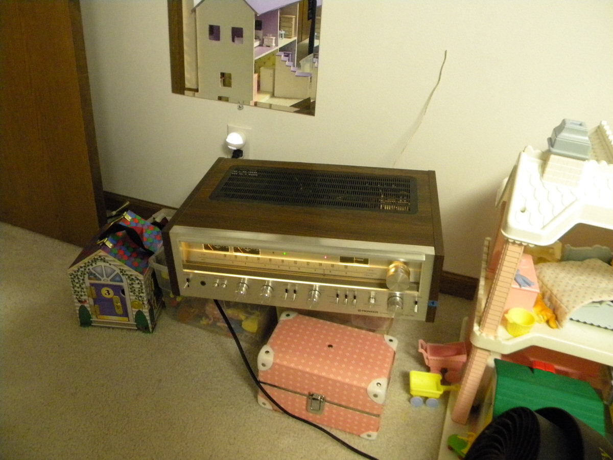
In lieu of a thousand words:

SX-780RunIn.jpg
 
I grabbed one of my 780s out of the stack and plugged it in at the grandkids' play room (AFCI). It hadn't been run for a while anyway. I'll leave it on for several hours just for grins, but it engaged the speaker relay about 4 seconds after power-up, just like always.
 
Incidentally, if you know anyone over at Malloy Electric, tell them I said "Hi" after you ask them about switching supplies and interference. Remind them of the problems at ADM in Marshall, MN, and be prepared for a long story (take a brown-bag lunch).

Like I mentioned previously, line-side noise is a LOT bigger problem than anyone who sells crappy AV, computer, and other consumer-grade junk wants to admit, but it's becoming such a problem that several of my latest installations required low-harmonic drives and supplies (or faced penalties from the utility providers). They would love to install a handful of 1.5MVa or larger ESS transformers on your site at YOUR expense.

Wichita, Harrisburg PA, Pawling NY, Henderson NC, Kansas City, Millsboro DE, Fort Hood TX, among others, require (by code) ULH equipment because of all the noise generated by crappy equipment. And you don't want to piss off the girls and boys at Ft. Hood - They have M1A1s with turrets that spin ALL the way around...
 
Incidentally, if you know anyone over at Malloy Electric, tell them I said "Hi" after you ask them about switching supplies and interference. Remind them of the problems at ADM in Marshall, MN, and be prepared for a long story (take a brown-bag lunch).

Like I mentioned previously, line-side noise is a LOT bigger problem than anyone who sells crappy AV, computer, and other consumer-grade junk wants to admit, but it's becoming such a problem that several of my latest installations required low-harmonic drives and supplies (or faced penalties from the utility providers). They would love to install a handful of 1.5MVa or larger ESS transformers on your site at YOUR expense.

Wichita, Harrisburg PA, Pawling NY, Henderson NC, Kansas City, Millsboro DE, Fort Hood TX, among others, require (by code) ULH equipment because of all the noise generated by crappy equipment. And you don't want to piss off the girls and boys at Ft. Hood - They have M1A1s with turrets that spin ALL the way around...
Thanks for the pic! If the grandkids know what good audio sounds like, they'll ask you to connect up some good speakers and leave that 780 right there!

Yes, I've worked with several of the Malloy guys in the past - we had them rebuild many of our higher-horsepower motors at my old job. They were only two blocks away from my old place of employment, so getting motors back and forth was a pretty fast operation.

Interesting about the harmonic interference from frequency drives. I know we have several of them in the building. There's literally tons of scientific equipment in the building and I know there have been problems with experiments where isolation from the outside world is required - these are in cubic-yard-sized Faraday cages. I never thought about harmonics from frequency drives being back-fed into the building power grid. I know my predecessor highly-stressed the need for conditioned power outlets and I don't know if there are any in the building. If there are, they're not in the labs where they need to be. We may very well end up talking with our friends at Malloy to see if they can do a debugging. I did have my o-scope connected up to incoming power and ran the voltage and frequency dials all over the place looking for some kind of goofy interference, but didn't find any. Would an o-scope capture harmonic interference on a power line, or is there some specialized equipment needed for it?
 
Small world, eh?

Most 'scopes would be fast enough to catch switching noise on the 60Hz source, but you would have to zoom in on the leading/trailing edges and zero-crossing points. With some scopes it can be tricky setting the trigger low enough to see that without losing sync completely.

Unfortunately, the 780 is still running (no speakers) at about 30% volume with no problems. I don't think it's a design problem on "normal" power and doubt that the ACFIs are affecting it much, if at all. I've got a Schneider/Square D load center, so it's pretty mainstream. I don't know if Eaton, C-H, or any other equipment has demonstrated problems in this area, but haven;t researched them either.

You might be in for an ESS isolation transformer Like This if the problem persists. I don't know how fast the AC detection portion in the PA3004 actually is, but it could be an issue if there are line irregularities.

 
Small world, eh?

Most 'scopes would be fast enough to catch switching noise on the 60Hz source, but you would have to zoom in on the leading/trailing edges and zero-crossing points. With some scopes it can be tricky setting the trigger low enough to see that without losing sync completely.

Unfortunately, the 780 is still running (no speakers) at about 30% volume with no problems. I don't think it's a design problem on "normal" power and doubt that the ACFIs are affecting it much, if at all. I've got a Schneider/Square D load center, so it's pretty mainstream. I don't know if Eaton, C-H, or any other equipment has demonstrated problems in this area, but haven;t researched them either.

You might be in for an ESS isolation transformer Like This if the problem persists. I don't know how fast the AC detection portion in the PA3004 actually is, but it could be an issue if there are line irregularities.
It's too bad there isn't a complete schematic for the inner-workings of the PA3004. Oddly-enough, if I removed R12 and bypassed R11 on the protection board, the relay cycling stopped, and I would still have about 0.65vac on pin 7 of the PA3004 - same as I always had - even with the resistors in place. I don't know if that's a modification that could be permanent, but from the behavior of the receiver and the voltage measurements I took, I didn't see where it was hurting anything.

Another thing - the receiver(s) would work for maybe a couple hours at a time when they were at the shop - usually Monday mornings. This behavior would sort of negate the AFCI theory, since you would assume they would always be problematic. But the frequency drives in the building all run blower fans, which are regulated, so they'll speed up and slow down from outdoor wind gusts, building air pressure - depending on how many/often doors are opened, and lots more variables. That erratic behavior of the frequency drives would better-fit the receivers sometimes/sometimes not working.
 
It's been about 6 hours, and the 780 is doing just fine at about 1.5W on the VU meters.
 
It's been about 6 hours, and the 780 is doing just fine at about 1.5W on the VU meters.
I would say you probably have the all-clear for the AFCI working okay with your SX-780. I ran my original SX-980 at home for about that same amount of time total. I pushed around 60 watts peak for a couple hours (according to the meters, at least) using these monsters:
20180929_162012 (Small).jpg

They're Klipsch Cornwall IIs - the college was going to toss them in the junk. I was luckily alerted by another staff member. Shown in front of the spare couch, since we still haven't quite figured out where to put them due to their size, but we don't want to sell them, either. That speaker on the right had a nasty, sticky stain on the cloth grille. One can each of tan and off-white spray paint improved things dramatically. I used to have rental property, and the tenants would do nasty things to carpet that wasn't very old. Spray paint did wonders.
 
the 780 is a little different at the pa3004 .. pin 7 is 0v on the schematic .. AC is done with 2 x1 meg resistors divider .
 
the 780 is a little different at the pa3004 .. pin 7 is 0v on the schematic .. AC is done with 2 x1 meg resistors divider .
That's interesting. I would have thought the same voltages would have to be present on the same pins for normal operation - regardless of what receiver the PA3004 is installed in.
 
It's too bad there isn't a complete schematic for the inner-workings of the PA3004. Oddly-enough, if I removed R12 and bypassed R11 on the protection board, the relay cycling stopped, and I would still have about 0.65vac on pin 7 of the PA3004 - same as I always had - even with the resistors in place. I don't know if that's a modification that could be permanent, but from the behavior of the receiver and the voltage measurements I took, I didn't see where it was hurting anything.

I seem to remember (maybe) a SX-1280 where we went round and round about the protect circuit and the AC ("turning off") as well.
ANOTHER AFCI debacle that disproved AFCI's as the problem.

The PA3004 pin 7 may have about 20k equivalent input impedance due to calculated current draw (35 uA??) and voltage drops.

as for the sx-780 schematic, I see that and it is a factory drafting error for the model - it is repeated over several sources.
IT HAS to have a minimum of 0.7 volts with zero crossings to bias the junctions on and off to detect AC.
 
I seem to remember (maybe) a SX-1280 where we went round and round about the protect circuit and the AC ("turning off") as well.
ANOTHER AFCI debacle that disproved AFCI's as the problem.

The PA3004 pin 7 may have about 20k equivalent input impedance due to calculated current draw (35 uA??) and voltage drops.

as for the sx-780 schematic, I see that and it is a factory drafting error for the model - it is repeated over several sources.
IT HAS to have a minimum of 0.7 volts with zero crossings to bias the junctions on and off to detect AC.
Okay, that makes a little more sense - my assumption about the universal operation of the PA3004 was correct.

An observation I keep going back to is that when I provided AC power to the protection board using an external wall wart, the relay operated normally. I'm wondering why that would be? If we're talking about some goofy harmonic frequencies causing the relay cycling, then does it come down to the transformer and how it's wound? Or is it that the receiver's transformer's windings are, at a point, tied to the same ground that's shared by pin 3 of the protection board? Or neither? Or both?

Edit: I just realized that the wall wart was also grounded to pin 3 of the protection board (with the receiver's 21vac source removed from pin 1) - duh. Still different transformers = harmonics might not be induced in the secondary of one transformer, but they are in the other?
 
Last edited:
one thing stuck with me .its when you removed r12 the relay behaved .. its just with r12 being connected to ground that made me wonder about this . i couldn't see why or how that could make a difference ..
p.s @markthefixer are the 1 meg resistors correct values in the 780 schem ?
 
A
one thing stuck with me .its when you removed r12 the relay behaved .. its just with r12 being connected to ground that made me wonder about this . i couldn't see why or how that could make a difference ..
p.s @markthefixer are the 1 meg resistors correct values in the 780 schem ?
Actually, removing R12 alone didn't make a difference. Bypassing R11, which is only a 1.5K resistor AND removing R12 stopped the relay cycling. The weird thing about that is, once R12 is removed, there's 471.5kohms of resistance between pin 1 of the protection board and pin 7 of the PA3004. Yet, when I bypassed the 1.5K resistor (a mere fraction of the total resistance), still leaving 470K of resistance in place, the relay stopped cycling. Very odd. I ohmed out both of the originals - R11 & R12 - both checked correctly. I subbed in new resistors in their place - same scenario. I also test R8 - it checked normal at 470K. That whole thing looked fishy, but I checked and rechecked, and it proved out - R11 had to be bypassed. I tried piggy-backing R8, but got nowhere with that. For whatever reason, removing 1.5K of resistance by bypassing R11 (along with removing R12) was the final key to stop the relay cycling.
 
all i can figure is in normal operation when AC is removed the relay switches off just before the DC collapses . and maybe why it cycles with AC removed and DC still present .. just a late night thought ....
 
Do the voltage divider calculations as if the IC's pin 7 AC input being a 20k ohm resistor to ground, and imagine the various voltage dividers as you change resistances.

Now remember - my calculations showed 20k, but things went around that value all the way down to 12k and 58 vs 35 uA input current.So it's not ironclad 20k ohms.
 
A

Actually, removing R12 alone didn't make a difference. Bypassing R11, which is only a 1.5K resistor AND removing R12 stopped the relay cycling. The weird thing about that is, once R12 is removed, there's 471.5kohms of resistance between pin 1 of the protection board and pin 7 of the PA3004. Yet, when I bypassed the 1.5K resistor (a mere fraction of the total resistance), still leaving 470K of resistance in place, the relay stopped cycling. Very odd. I ohmed out both of the originals - R11 & R12 - both checked correctly. I subbed in new resistors in their place - same scenario. I also test R8 - it checked normal at 470K. That whole thing looked fishy, but I checked and rechecked, and it proved out - R11 had to be bypassed. I tried piggy-backing R8, but got nowhere with that. For whatever reason, removing 1.5K of resistance by bypassing R11 (along with removing R12) was the final key to stop the relay cycling.
Looks like the PA3004 pin 7 is high impedance and only a few microamps are needed to trigger to 'AC present' condition. High impedance would make it more sensitive to noise. With 18vac on the supply side of the SX-980 R 8 the PA3004 pin 7 would have about 38 microamps flowing, and the signal would 'clip' at +/- ~ one PN junction voltage, exactly like MTF indicates above (post 253). And PN junctions are not linear.
A small symmetrical AC signal would look like 0v to a DC setting on a DMM.
When the cycling stopped was the relay open or closed (released or pulled in)?
 
Last edited:
Back
Top Bottom